So ... after having tested my Arduino current & temperature sensor for a while (see this post), I had the idea of recreating it in a more compact and replicable way using the MQTT + NodeMCU paradigm I was explaining lately (namely, in this post).
So I took on rewriting the Arduino C code in Lua, and check :
- if it was even possible with the NodeMCU capabilities
- if it would work better than the Arduino version
The problems I had with the Arduino version were mainly due to the crappy WiFi chip that was on the WiFi Shield : the CC3000 (TI page here — not recommended for new designs anymore, anyway)
Not only was its connectivity deceiving, but the API was quite obscure and not really satisfying. The fact that you had to use older versions of the IDE to compile the code and/or to update the firmware was quite disappointing too.
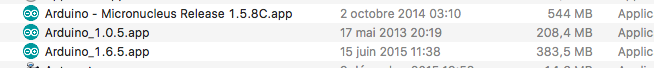
Compiling against specific Arduino versions can be quite ... unnerving ...
The Lua code
Translating the program to Lua just boiled down to rewriting it from scratch : the WiFi API is not the same, I had to code a 7-segment lib and the leds have a quite straightforward API.
The 7-segment needs to be given a specific bitmask (as per the C lib, here) so I simplified the process to have a reusable code — here is the relevant part for the communication :
local module = {}

local numbertable = { 0x3F, 0x06, 0x5B, 0x4F, 0x66, 0x6D, 0x7D, 0x07, 0x7F, 0x6F, 0x77, 0x7C, 0x39, 0x5E, 0x79, 0x71}
local displaybuffer = {}
local numericDigits = 4 -- available digits on display

local function sendSingleValue(addr, reg, value)
  i2c.start(0)
  i2c.address(0, addr , i2c.TRANSMITTER)
  i2c.write(0,reg)
  i2c.write(0,value)
  i2c.stop(0)
end

local function sendDisplayBuffer(addr, reg)
  i2c.start(0)
  i2c.address(0, addr , i2c.TRANSMITTER)
  i2c.write(0,reg)
  for i=1,numericDigits + 1 do
    i2c.write(0, bit.band(displaybuffer[i],0xFF))
    i2c.write(0, bit.rshift(displaybuffer[i],8))
  end
  i2c.stop(0)
end

local function writeDigitRaw(d, bitmask)
  if (d > numericDigits + 1) then
    return
  end
  displaybuffer[d] = bitmask
end

local function writeDigitNum(d, num, dot)
  writeDigitRaw(d, bit.bor(numbertable[num+1], bit.lshift(dot, 7)))
end
Then, the float to bitmask conversion was intense too (see the full code here).
Driving the pixels (they are WS2812 pixels — see the datasheet here) was quite easy — there is already a library for this in the custom firmware for the NodeMCU.
As for the rest, it was a matter of finding the correct documentation of each library and bit of code. I ended up with a viable solution that incorporated all the specifics of the old design (Arduino) + new fonctions, especially around the MQTT communication now that I was using it.
See the repo for details : https://github.com/tchapi/NodeMCU-Energy-Monitor
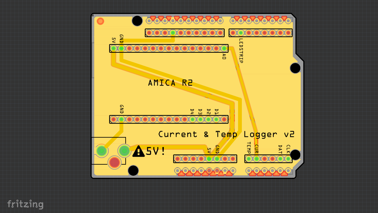
A NodeMCU in Arduino form-factor
As I previously had designed a board for the sensors, leds, and screen, I did not feel like redesigning it all the way for the NodeMCU pinout.
Here is the version I had already :
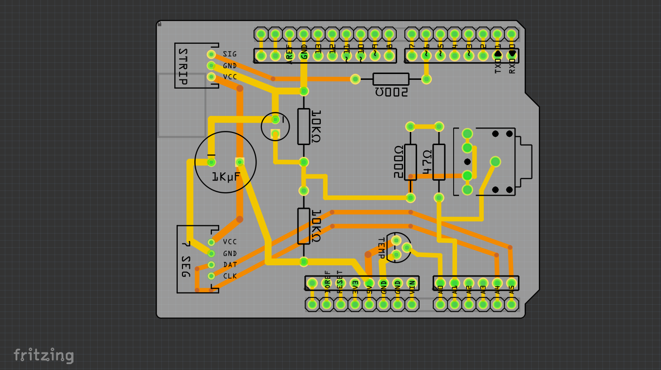
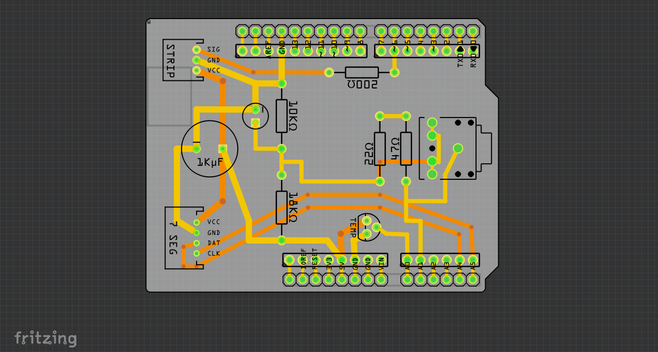
The only things I needed to change was the voltage divider, since it would work at 3V3 now (the ADC of the NodeMCU is a 10bit 3V3 ADC, not 5V). The change involved soldering two different resistors :
- one 18 kΩ instead of 10 kΩ
- one 22 Ω instead of 200 Ω
And Boom. Done (updated schematics for reference) :
So in the end I thought : why not creating a kind a NodeMCU board that would be in an Arduino UNO form factor ? That proved quite easy. In fact, I just had to route the NodeMCU pins I used to the correct Arduino ones.
Except for the temperature sensor. The NodeMCU has only one ADC pin, and that is used already by the current sensing mechanism, so I could not use it. I decided to change the temperature sensor and try one of these DS18B20 that have one-wire capability :
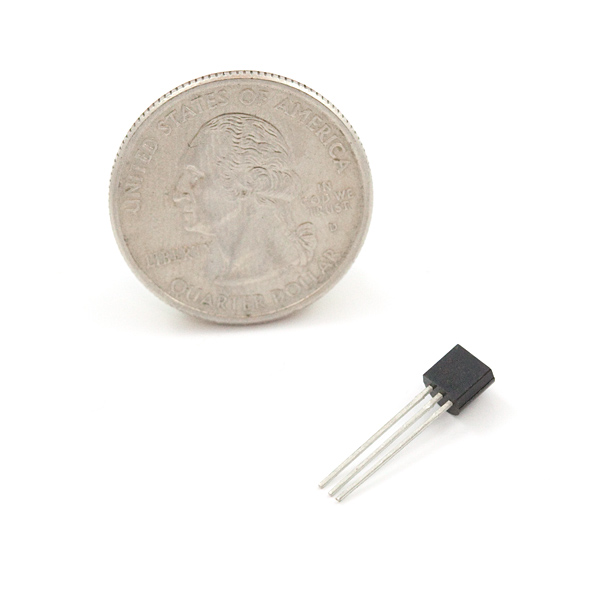
Image courtesy of Sparkfun
1-wire is pretty convenient and the NodeMCU has pins that can use this bus, so this was perfect. The replacement didn't need that much rework, just a little resistor bridging the +3V3 and the signal, that I put directly in the cable.
Fortunately, I could make everything "work" in 5V. Digital inputs are 5V tolerant (source here, though it seems controversial.. I will tell you if something burned at some point ...). The only pin that needed real 3V3 was the ADC, but as previously covered, I changed the voltage divider to accommodate for that.
So :
This is pretty basic. It's just wire... and a DC input connector
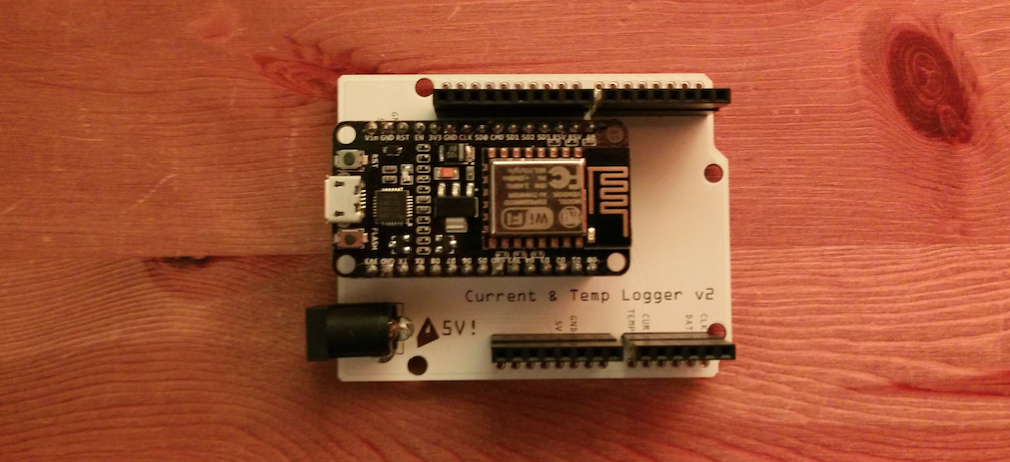
The board with the mounted Amica on it
Note that I had to solder extra long headers on this board to heighten up the previous board above the NodeMCU. Just take two headers, plug them together and solder it, it works well.
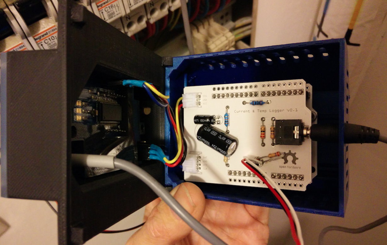
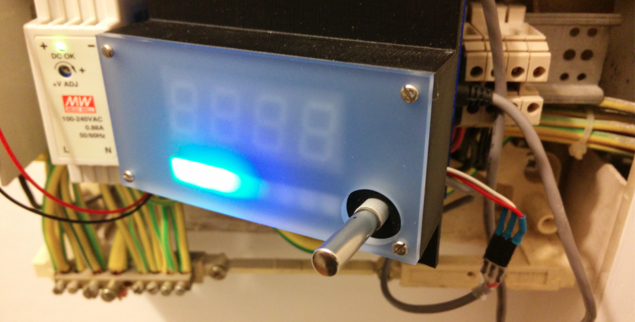
Mounting in the casing
As I had the same holes in the board, mounting it into the actual casing I had designed previously didn't create any problem.
I actually had more head room for air to flow in the box, so a much better electronic cooling, which is nice !
No more antenna
The NodeMCU board has an onboard antenna, directly on the PCB. So no need for an external antenna. Which is pretty cool since I can now use the hole I had for it for the temperature sensor (that has roughly the same diameter — I had bought a waterproof version that is enclosed in an aluminum cylinder) :
Here's the one from Adafruit that I bought (see here) :
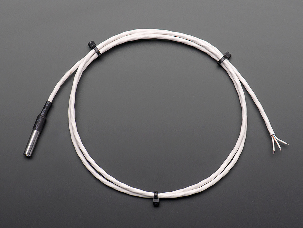
Image courtesy of Adafruit
The only other noticeable difference is that the side holes for power and USB do not correspond anymore. Luckily, I can still plug the power in. But I have to unplug the boards if I want to plug the USB cord back in. Not a big deal, though.
The Server code (Node.js)
The server code needed some update to retrieve the info via MQTT and not via a simple GET command. This was really straight forward so I'll point out to the actual code if you want to have a look. Nothing really fancy as an MQTT library exists for Node and does the job (namely, npm install mqtt).
See here for details : tchapi/NodeMCU-Energy-Monitor/tree/master/Server
The Android app
Just for fun, I created a very simple "dashboard" for Android — so simple it only displays the info and has 4 buttons to interact with the device. It comes pretty handy if you want to turn off the display (it can get pretty bright) or just get a glimpse at the consumption while away.
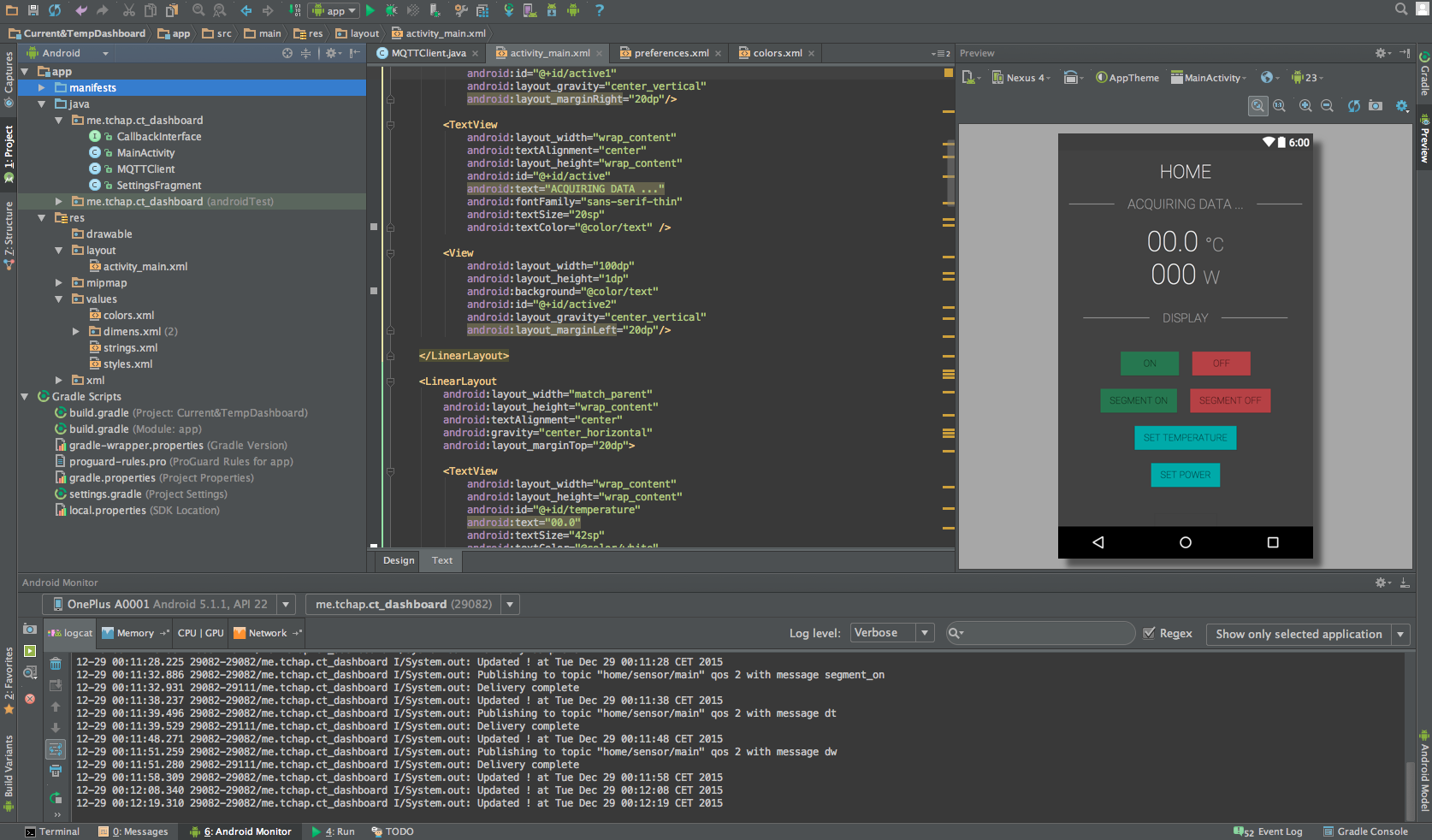
The code itself is also on github; It uses the PAHO Eclipse MQTT library that can be found here : https://www.eclipse.org/paho/clients/android/
The joy of MQTT & NodeMCU
MQTT is a really fantastic way to interact with sensors / devices like this one. I embedded functions to be able to display things on the screen of the device so I can check very easily if the device is online, and responds well.
The QoS principle makes it also easier to account for bad signal, corrupted data and the like. It's a plus compared to the previous first version where the device was controlling the communication via doing a simple GET request.
The NodeMCU gives me a lot more control on the device, and more headroom to code interesting stuff.
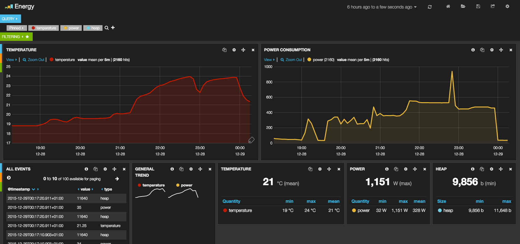
With this implementation, I still have about 12kb of free heap space for additional functions, and as I can monitor the heap size, I can detect if my code leaks (not the case here even though the size has fluctuated ).
All in all, it looks like a very neat upgrade from the previous version. It's now live and we'll see if problems arise in the future with it, but so far it has proven very stable. I have a bunch of NodeMCUs here so I guess I'll use this little board more and more for this kind of projects.
If you have any questions or comments regarding the code / the whole thing, don't hesitate!