While developing for the IoT2040 from Siemens (see the product page), I was having difficulties with the I2C bus; specifically, some peripherals were slow to respond or somehow buggy and the bus was becoming unresponsive.
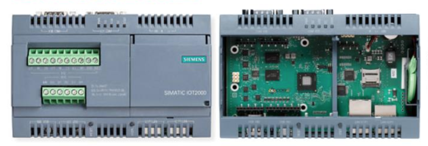
On this device, the I2C bus is behind an extender, and it seems not very robust when devices go berserk.
So I was tasked with finding a way to "reboot" the I2C bus if it found itself in a undefined state or if a peripheral was squatting the bus.
What came to mind was to do a power cycle so that the unrespectful devices could be powered off and rebooted fresh, generally freeing the data lines and prompting the bus to reset itself properly.
The naive solution I came up with was a simple dual MOSFET circuit that could allow for a software power cycle to be done via a control pin of the microcontroller that I was using (in this case, a Galileo Gen 2 — this is what is on the Siemens IoT20XX series).
A simple dual MOSFET solution
I had being advised to use a dual MOSFET, specifically one N and one P, to act as a switch to power on and off my I2C slaves.
I settled on the FDS8958A Dual N&P-Channel PowerTrench MOSFET from ON (Fairchild) (datasheet). There is no application schematics in the datasheet but something along those lines (adapt the R1/R2 values accordingly) should work as expected :
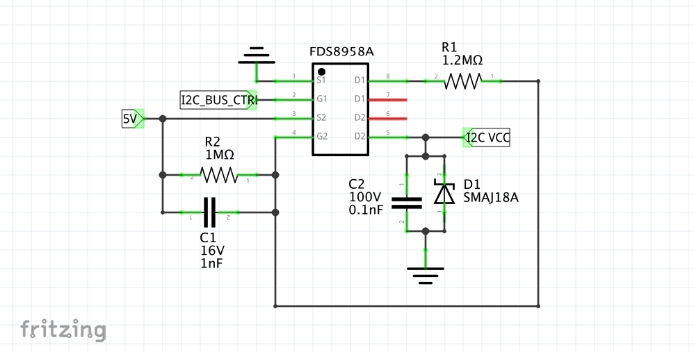
(the schematics is quite messy since I only had a standard 8 pin package chip and not a differentiated P and N component on Fritzing)
5V is my power source (we are using the Galileo Gen2 in 5V), I2C_BUS_CTRL is the control pin (HIGH means MOSFET is active), and I2C_VCC is the 5V output (all have the same GND) that is driven by the control pin.
The two middle pins D1 and D2 of the chip are not used as they are in fact redundant.
This works quite well, as the circuit is very fast (~10ns) and the output very steady. Setting the pin HIGH would power up the I2C slaves, and LOW would shut them down;
BUT
We then tried this circuit in a real world situation where the bus was used. And it turned out quite problematic, for various reasons :
- when powered down, some I2C slaves pulls the SDA and SCL lines LOW (~ 0.7V), which disables all traffic on the whole bus. I don't know if it's a standard behaviour but it certainly is not consistent accross the peripherals that I have
- the expander did not seem to be able to recover from a powered down I2C slave correctly (and the driver was not happy about it). This may be due to the fact that the lines were driven low
- Some low power devices actually act like they are still powered from the SCL line, which is unsettling. It defeats the whole purpose of the MOSFET since the peripherals does not really go through a power cycle
At the end of the day, power cycling the I2C slaves was causing more problems than before : the bus was unusable and the only option was a hard reboot on the IoT20XX.
An I2C repeater to the rescue
So I had this idea of cutting the I2C SDA/SCL lines too when powering down the slaves so as to be sure that they were really off the bus.
This would ensure that a powered-off slave would not prevent the bus from operating correctly.
I first tried the TCA4311A (datasheet). It's a neat little bus buffer that is specificaly designed for hot-swapping I2C slaves planes; I figured this is exactly what I wanted.
The application diagram was pretty straightforward :
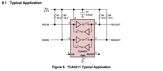
(Taken from the datasheet)
Unfortunately this chip seemed to have a problem with the SMBus protocol. Specifically, all words were not transmitted correctly (whereas all single bytes were properly received by the slave). I had no access to a scope at the time so it was difficult to know exactly why though and to debug, but I guess this could be linked to the pre-charge circuitry (see §11 of the datasheet).
So I unsoldered my TCA4311A and (horribly) replaced it (please don't judge me) with a different kind of bird — an I2C repeater — to test if this would be better :
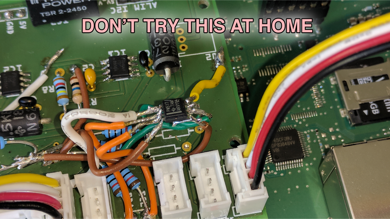
It's the TCA9517 (datasheet), that acts like a buffer too but in a different fashion.
The schematics to include it is pretty standard, as per the previous I2C bus buffer :
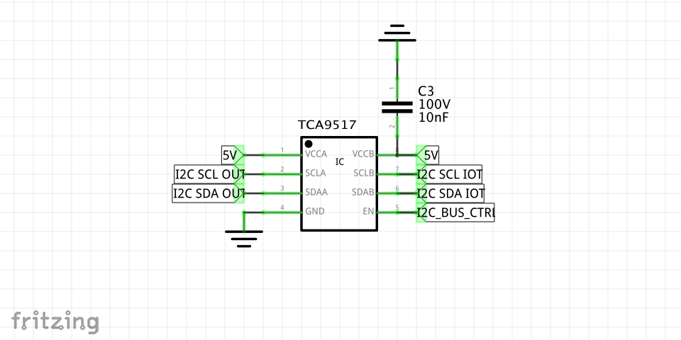
I2C_SCL_IOT and I2C_SDA_IOT are on the master side, whereas I2C_SDA_OUT and I2C_SCL_OUT are on the slave side. The I2C_BUS_CTRL is the same net as for the Dual MOSFET.
And this worked !
Of course, some pull-ups are required on each side of the buffer (I used 4,7kΩ but YMMV) :
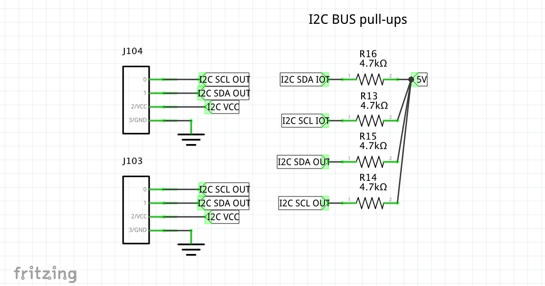
With these two chips : the dual MOSFET and the bus repeater, I can now totally disconnect the needed I2C slaves when they behave badly. By setting one pin of my microcontroller LOW then HIGH, the VCC line of the slaves is down to GND and the slave part of the bus is deactivated, then reactivated as if it was connected for the first time.
Comments welcome as usual if you find an error or if you want to add something to this.