A Musical and Retro-gaming installation and live event.
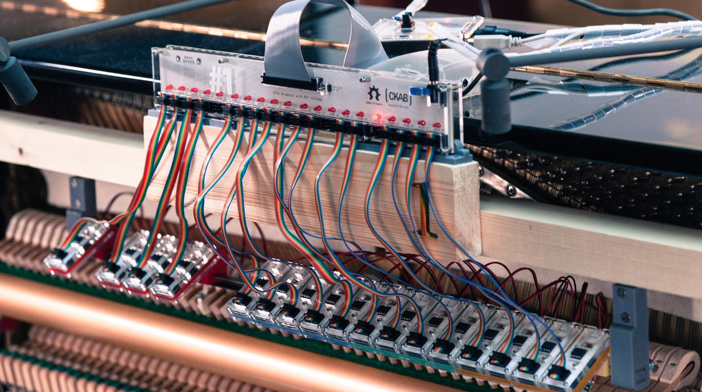
Update: We can hardly believe it, but we made it to the front page of Hacker News! Take part to the discussion here!
Update 2: We would like to give immense credit to pianists Alvise Sinivia and Léo Jassef from the Conservatoire National de Paris, who appear in the video above. It was an absolute delight to see and hear them play/fight during the public event.
The concept was pitched for the reopening of the Maison de la Radio, French’s principal and historical radio building situated in the heart of Paris.
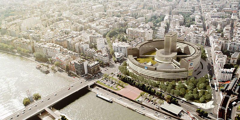
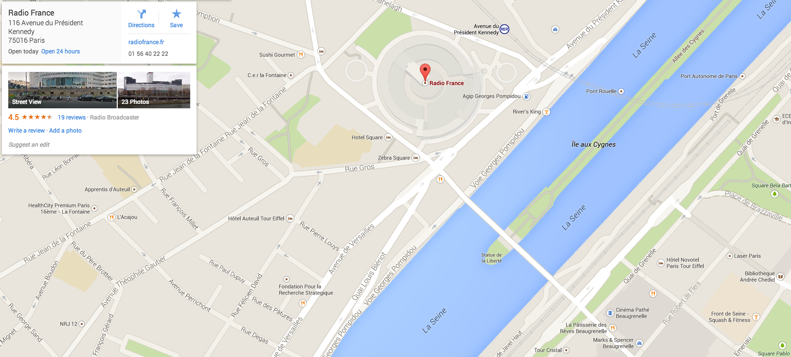
(images courtesy AS — Architecture Studio and Google Maps)
The building has been the home of the French public radio stations for more than 50 years and recently reopened to the public as a cultural space, offering a wide spectrum of entertainment choices such as live concerts, workshops, live radio shows, etc.
For the reopening function, Jean Weessa and Mélanie Pennec (from DDB and now Altmann + Pacreau) originated the idea with the aim of giving an alternative visual identity to music (as a general concept).
Another underlying idea was to reconcile the general public with classical music, and moreover classical instruments such as the piano, giving them a different insight on what notes, chords, and scales could “create”.
The idea was gladly accepted by the Maison de la Radio and we (Eric and I) were tasked with the realisation of the installation.
The project was on a very tight schedule. The go was given on the 1st of October; the shooting of the teaser video was to take place on the 12th of November and the live event on the week-end of the 14/16th of November.
We’re going to detail chronologically the steps we took, with some technical details. We hope you will enjoy reading and get motivated to use this project somehow!
D - 41
Choosing the sensors
The first step was to understand how we could possibly acquire the information of the striken notes from a classical piano.
In a classical piano (upright or grand), the notes are striked by a hammer that bounces on the string to create the sound. A complex mechanism allows for fast repetitions of keys by maintaining the hammer at a short distance from the string, while lowering the keyboard key a bit for a quicker stroke by the pianist.
We will not delve into the details of the system but the key elements that seemed of interest are:
- the hammer rest rail
- the hammer in itself
- the key stick underneath the hammer
The type of piano that we’d be using was not clear at this point. While a grand or semi-grand piano seemed the right choice, an upright piano was easier to “hack” in various ways. We assumed we’d go with a grand piano and see how it goes (The hammer system is different on a grand and upright piano, see below).
Grand piano
The string is on the top, the hammer is inside the body of the piano:
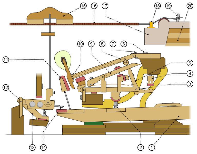
(images courtesy of ejunrau)
Upright piano
The hammer is outside the string and more accessible:
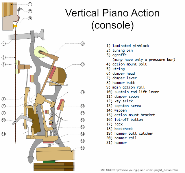
(images courtesy of ejunrau)
To record an event, many sensors are available on the market. Among the first ideas, we could have:
- put a pressure resistor on the key to sense the finger of the pianist striking the note
- put a motion detector sensor (accelerometer, gyroscope…) on any moving part for each key
- put a knock sensor (piezo or eq.) on a moving element
- hooked up a MIDI system to the piano
- recorded the sounds via a microphone and analyzed the sound / harmonics
- etc.
As the available sensors choice was quite important, we had to review and evaluate each possibility with care since it was an early choice to make that would have implications all along the project:
(following sensor images courtesy of Sparkfun)
Pressure resistor
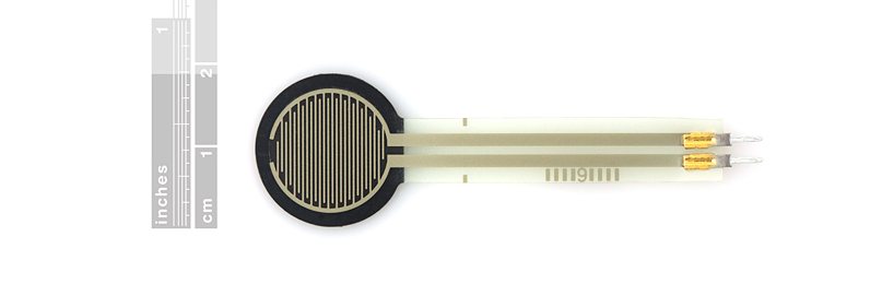
A pressure resistor is a piezo resistive sensor that changes value (within a range) when you push on it, in a reversible way. Some “touch” interfaces are built this way (though now touch screens take the lead).
For instance: Piezo resistive sensor on Sparkfun
The idea was to place one resistor (they are extremely flat, about 500µm) on each key to sense the pianist fingers activating a key.
✓ Pros:
- it’s a resistor: it’s sturdy, it’s cheap, it has no critical part
- it’s very thin, flat
- it’s easy to integrate in a circuitry
✗ Cons:
- it’s “on the outside” so it needs to be good-looking
- you can feel it when you press the key
- it’s quite sensitive to the specific place you put your finger on when you play a note
Discussing with pianists, it seemed that the finger placement on a key when you play is quite variable, and would lead to a majority of keystroke not to be recorded by the system, which is a problem.
At the end of the day, it was not a good choice for us as differents pianists (experts, kids, …) would not have pushed it at the right place.
Motion detector sensor
We though about the accelerometers and gyroscopes quite early in the project discussions.
A single axis accelerometer like this one could record a large change in acceleration when the hammer hits the chord (if correctly placed on the hammer).
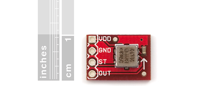
With a correct reference voltage (i.e. threshold), we could a priori isolate the hammer hitting the string from the other movements of the hammer (especially the hammer leaving its rest bar and coming back to it).
✓ Pros:
- it’s a closed component: it’s quite sturdy
- it’s very small
- it’s quite easy to integrate in a circuitry
✗ Cons:
- it’s expensive (we would need 40 of them approx…)
- if placed on a hammer, it’s quite heavy so it would modify the course of the hammer and probably the dynamics of the sound
Knock sensor
Another type of piezo element is a polymer film loaded with an inertial mass (cantilever-type vibration sensor) that detects vibrations and knocks like this one:
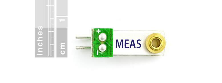
✓ Pros:
- it’s super light (0.5g) and small
- it’s easy to integrate in a circuitry
- it needs no external power (it acts as a voltage source in series with a capacitance)
✗ Cons:
- it has a moving part
- it can deliver a very high voltage (>90V) if hit hard
These sensors provide an interesting solution: they are very light (0.5g) and like the accelerometer, easily record a change in acceleration (if given the good threshold as well).
MIDI system
A MIDI system comprised of a mute rail and a MIDI encoder was the easy “out-of-the-box” system that we could have used.
The mute rail intercepts the course of the hammers and records its force to create a MIDI version of what you play, available to hear or to process in a little box above the keyboard.
In this case, the sound of the piano is no more created by the strings, but recreated by the MIDI system.
✓ Pros:
- it’s easy to install and it’s an already existing solution
- the notes are available readily and accurately
✗ Cons:
- it’s not the sound of the piano anymore
- it costs … a lot
- it’s not that easy to find in Paris in a fortnight
The main problem that we identified was that it was “not in the scope” to be used for this particular project. We wanted to keep the real sound of the piano and not use what we could call an “electronic instrument”. The challenge was much more interesting if the piano was a real analog piano, without add-ons.
The price tag was also a no-go, anyway…
Microphone
Last but not least, we could go the computational route, analysing the sound of the piano through a well-placed microphone and deduct the keys and chords hit.
✓ Pros:
- it’s non intrusive
- comprehensive research exist on the subject
✗ Cons:
- it’s slooooow (see note below)
- it’s not 100% accurate
- the microphone would have caught background noise during a live event
A note on sound analysis and latency
The documentation of the “Audio to score” function of Logic Pro states: “Good results can be achieved using clearly identifiable, monophonic audio material. This function is best-suited to producing melody notes from a clearly sung non-legato vocal line.”
Well, this clearly isn’t our case and if Apple can’t do it realtime, I doubt we can easily find a way to do roughly the same thing on our own. Some other professionnal products like AudioScore state that they can transcribe audio in a realtime fashion but the forum users seem to be less enthusiast on the accuracy of the whole system.
Final choice
It’s important to note that the project was on a limited budget, and on limited time, and that we wanted to turn the process into a playful project for us, as well ;)
The latency in the sound analysis was quite a problem, that we couldn’t ignore. We thus eliminated the microphone quickly from the available possibilities. The MIDI system was also not the good choice for the project
The pressure resistor was too small and was not really resilient if the finger of the pianist was not really placed at the good place, so we decided to forget this solution.
Between the acceleromer and the knock sensor, we went the piezo route.
Since no power source is needed to make it work, the piezo needs only two cables to link it to the main system (more cables would likely prevent the hammer from moving since it is quite a light mechanical part).
Moreover, it’s cheaper than the accelerometer and has a greater sensivity.
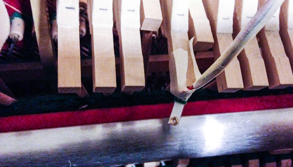
Preliminary tests after the choice showed that the sensor could be fitted on the hammer and record knock events:
D - 38
What console? What version?
We had to choose the version of the game and the console on which we’d hack the whole thing.
Street Fighter started in 1987 and has had a lot of different versions and releases. See the wikipedia article for more info.
The specifications indicated that we needed to find a sort of HD version of the game (so, no Street Fighter before III at least) but that it should be retro enough to be easily identifiable as a ’90s era arcade video game.
This is not as easy as it sounds.
We needed to choose a game on a console that was not too hard to hack, because of the limited time we had ahead of us.
The Super Nintendo was a known-to-be-hackable console but unfortunately the resolution of the game would have been too low for us. On the “next” generation of consoles, literature was a bit more scarce when it comes to hacking a controler.
In a nutshell, we had a choice to make between an Xbox, a Sega Dreamcast and a Playstation 2. These three consoles had a somewhat HD version of the game: Street Fighter Alpha 3.
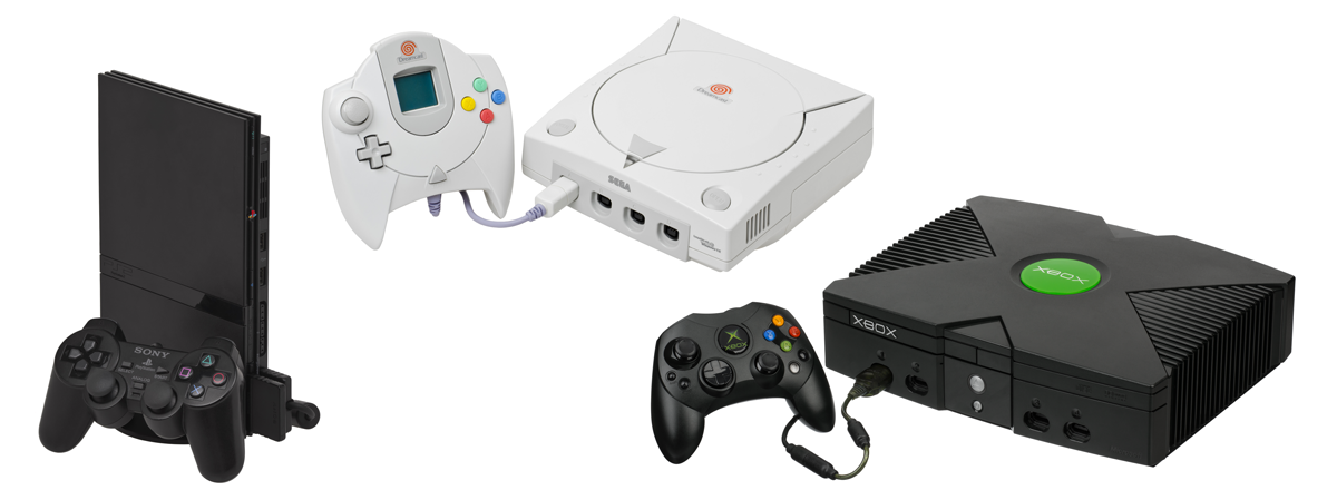
The Dreamcast console controler seemed quite hard to emulate — we could’t find any existing project to leverage, and the fact that it contained two extension slots warned us that it might be a pain in the a** to do.
Moreover, we had to settle on a console quickly to test things. And finding a working Dreamcast under some kind of warranty (like for instance sold by a gaming shop, so we are sure it works) in Paris looked complicated.
The Xbox seemed more appealing. Some mods already exist (Generally rapid fire buttons, drop shots, auto reload, etc.) and are sold in specialized shops;
But in our case we needed to replace completely the controler, not only enhance it. While some attempted to do this (see this fantastic tutorial), it involves creating a full-fledged USB controller implementing OHCI protocols and the like. So quite a lot of work. And many gave up before seeing the end of the tunnel apparently (see this thread for instance).
So, well, we hadn’t a good feeling about it.
Enters the Playstation 2. A quick search showed us that there was a lot of people using Playstation 2 controlers to control things: robots, PC games, etc., which is a good start. It’s not exactly what we want but it’s a nice hint that a community exist and that there is some literature on the subject (there’s even an Arduino library for that and a forum post as well for details).
The Playstation 2 is still an easy to find console in the gaming shops, at a good price AND in a very good condition (We all have friends that still own one and play on it regularly).
It seemed quite an obvious choice. Now let’s hunt one in the street of Paris!
Note: Why not an emulator?
Now, that’s a good question. We had it in mind for a while because it was obviously a good choice: no console hardware dependency, the controler could be practically anything as long as it could be attached to a Linux computer. But it was not fun. Yes, exactly, it was as boring as hooking up a MIDI instrument to a new Mac Pro.
More importantly, it may seem like we decided to go the difficult way but the real beauty of the project lied in the fact that we used an analog instrument and an original console in the process. Avoiding difficulty would have been the easy way out but was not fulfilling at all.
D - 35
First meeting: let’s play Street Fighter
I mean, when you have to work with something, you test it, right? Well, that’s what we did…
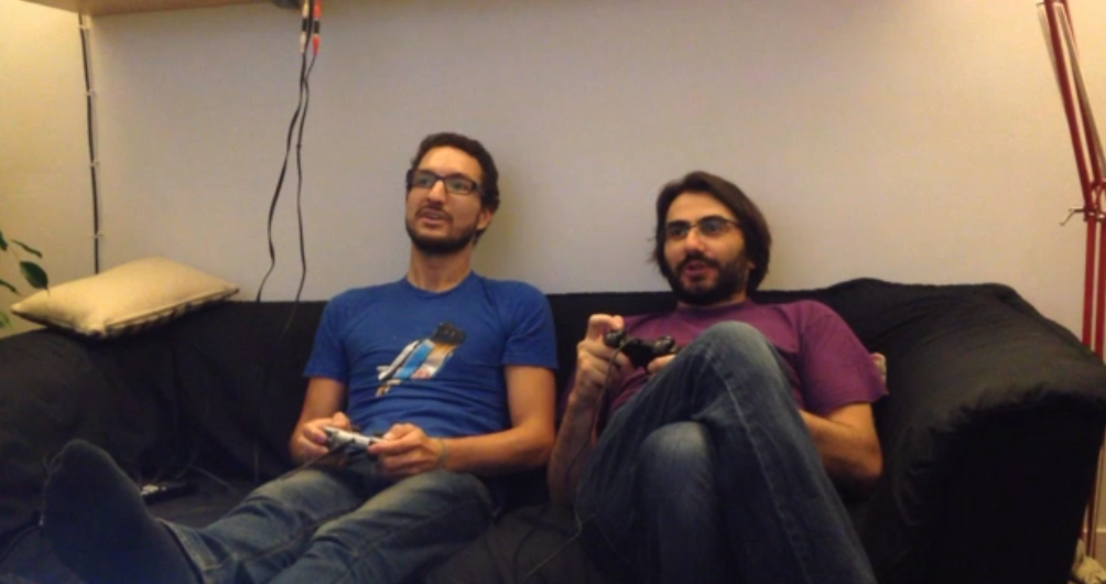
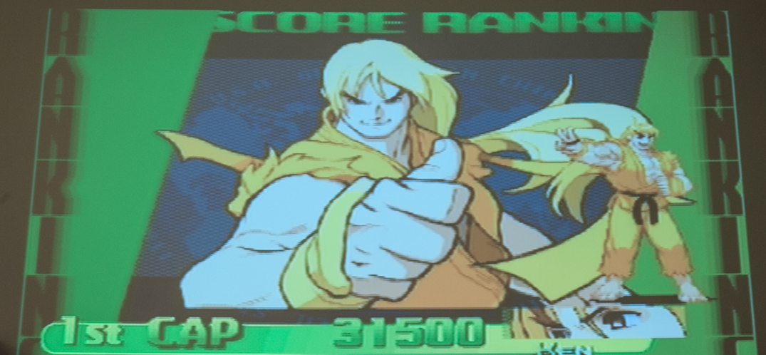
Granted, it does not look like we’re working too hard. But actually, this gaming session sparked the first of many discussions to determine how, exactly, we could achieve proper console gameplay using a piano. Definitely not as obvious as it could seem.
A simple solution would be to link every piano key to a controler button. This could be fairly easy to build, but seemed that it would lean way too much towards non-music, providing too much of a simple translation, instead of a metaphor. We wanted a system that would allow us to say: “If you’re a good pianist, then you’ll be a good gamer”.
This made sense in a lot of ways: a kid testing the system, just pushing some keys and not knowing piano at all would be the exact parallel of a kid not knowing how a console works and pressing randomly on the buttons.
Whereas a good pianist, playing a more complicated melody and sophisticated chords, would be the equivalent of a gamer perfectly understanding the game he plays and unlocking some special figures / combos / techniques in the game by pushing the right buttons at the right time.
Simply put, we had to find a way to translate what a good pianist would play into what a good gamer would play.
Also, the goal being having two players fight head-to-head, we needed to remember that two pianos would play music at the same time during a game.
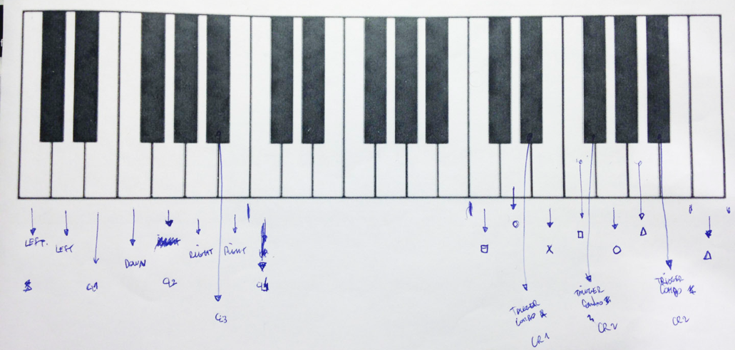
A preliminary draft of the keyboard mapping
Of course there are many solutions to reconcile these elements. We quickly agreed on a route that seemed quite natural and fun to us:
- focus on the left hands for the movements
- focus on the right hand for the actions
- chose a specific scale so that the two pianos playing at the same time would not sound too chaotic
Many pianists/gamers were on track with this and we didn’t really question the fact that the left hand should definitely be the “moving” hand.
As for the right hand, we followed a lot of advice from composers and gamers and decided to split the right hand octave into contiguous 3 or 4 keys zones for each action button on the Playstation controler.
But at this very moment a question arose: how many keys could we watch with our hardware?
Oh. Wait. We haven’t chosen our hardware yet!
D - 33
Choosing the hardware chain
Now, the question of “How many keys can we detect for one piano” was not benign at all, since we would need a hardware that could process that many inputs.
Each sensor (explained above) would take one input pin on any system, and to have a good gameplay we needed something like 20 piano keys.
We knew we needed some computational power as well. If we stayed in the range of small µcontrolers like the ATMegas, we would at least need the ATMega 1280 it seems.
We could use the Raspberry Pi B+, that was just out at the time, and that had a more powerful core but slightly less pins (40, not all useable, against 54 for the 1280).
Other options included ARM boards from other constructors (similar to the B+) or PIC µC for instance.
More importantly, we needed ~20 interrupts. And even if the ATMega1280 has more pins than an ARM board like the B+, it only has a few hardware interrupts. The other ones are software, just like for the Pi; so no competition here.
As well, the ATMegas and other equivalent µCs have limited program space, so we weren’t sure that we wouldn’t hit the limit during the coding; that would have been a big issue since time was a very important factor.
At the end of the day, we decided it was easier for us to work in a Linux environment with all the remote connection capabilities rather than compiling and uploading each time we wanted to push new code.
We chose the Raspberry Pi B+. The Raspberry Pi Model B was a good ARM board but lacked some evident features like a sensible isolation of the USB ports, that the B+ adressed quite well. The community was quite strong, and there was a very large base of open-source software that we could use to gain some time. Bingo.
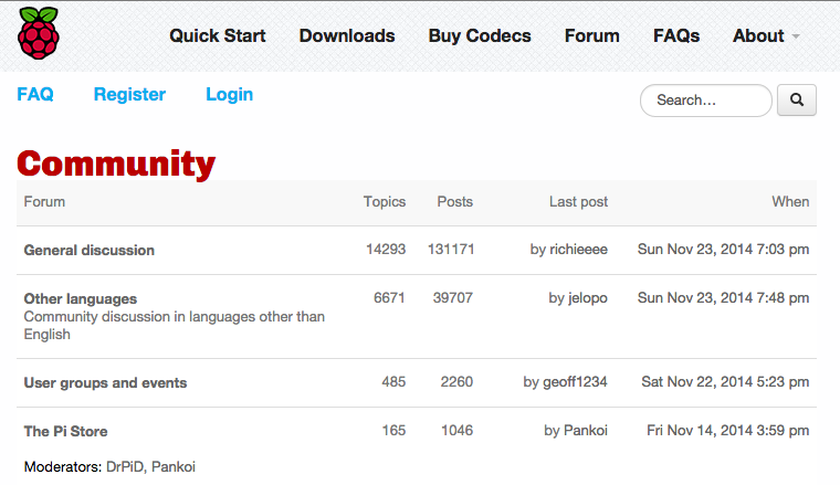
The home of RasperryPi.org forums
Another advantage of using a Linux-like environment was to be able to develop a scriptable firmware. That is, not only to create an interface between the electronics and the Playstation 2 in this particular case, but to create something wider and more versatile that could accept many input channels and, why not, different output channels as well.
As an example, that would mean that we could use a text file to play a specific song or a sequence of gameplay inputs, or use a MIDI file, and, on the other hand, use a different console or an emulator to see the result.
A note on open-source
We decided right away to go open-source and open-hardware for this project. It seemed indisputable that it was a somehow valuable thing to give back to the community of hackers/gamers/piano-players and considering the fact that we were going to use a lot of open-source parts in the process, the choice was obvious.
D - 29
A first firmware version
We were still debating on how to correctly “map” the keys to the game, but we had to keep going and look at all the other problematics of the projet so as not to lose our precious time.
So we fired up a text editor and begun writing some code to lay down the basis of a firmware for the thing.
It didn’t take long to choose Python3 writing it. While neither of us was more than remotely familiar with this language, we also knew that we could not afford a cumbersome compiling chain getting in the way of quick iterating, or hotfixes for the live event. We quickly became confident that Python3 would provide great benefits with regards to ease and speed of coding, and let us benefit of well-maintained modules fitting our needs.
The first version was targeted at debugging easily the bits and pieces involved in the hardware chain.
See the tree of the first commits to have a rough idea of what we needed to test.
Note: the project was prefixed with “SNES” because we unearthed old pieces of code around the Super NES. As per the following image showing a Super NES styled window. But it was quickly renamed.
TKinter was used to create a nice little interface so we could test the input and test the output as well (by pushing on the touchscreen).
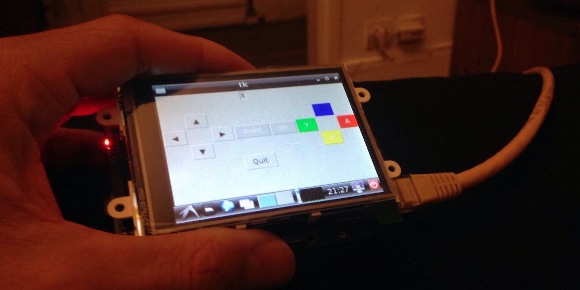
Once this little test interface created, it was easier to test the inputs (we only had one at the moment).
But a question was still unresolved: the Raspberry Pi B+ has 40 GPIO, but how many of these can we really use?
Quoting Matt from www.raspberrypi-spy.co.uk:
“The B+ offers 9 extra GPIO pins [compared with the B] which can be configured as inputs of outputs. This brings the total number to 26 (17+9).”
So 26, right? Well, it turned out to be not that easy when you want to use them ALL.
First of all, in order for SPI and I2C pins (02, 03 and 07 to 11) to be adressed as general purpose I/Os, it is compulsory to blacklist all modules that might be using it for anything else:
especially in /etc/modprobe.d/raspi-blacklist.conf:
blacklist spi-bcm2708
blacklist i2c-bcm2708

blacklist regmap-spi
blacklist regmap-i2c

blacklist snd-pcm
blacklist snd-bcm2835
blacklist snd-seq
blacklist snd-timer
blacklist snd-seq-device
blacklist snd-soc-core
blacklist snd-soc-pcm512x
blacklist snd-soc-wm8804
blacklist snd-soc-bcm2708-i2s
blacklist leds-gpio
which pretty much boils down to:

The same goes for /etc/modules, especially sound-related modules that have to be removed.
Then, the UART pins (14, 15 and 18), that are used at boot time to spawn a nice serial debug console. So we must disable the boot up and diagnostic output to the serial port:
A quick sudo vi /boot/cmdline.txt
dwc_otg.lpm_enable=0 console=ttyAMA0,115200 console=tty1 root=/dev/mmcblk0p2 rootfstype=ext4 elevator=deadline rootwait fbcon=map:10 4dpi.sclk=48000000 4dpi.compress=1
the above line becomes:
dwc_otg.lpm_enable=0 console=tty1 root=/dev/mmcblk0p2 rootfstype=ext4 elevator=deadline rootwait fbcon=map:10 4dpi.sclk=48000000 4dpi.compress=1
And we’re good! Second, we need to disable the login prompt:
sudo vi /etc/inittab
And comment out the last line:
# Spawn a getty on Raspberry Pi serial line
# T0:23:respawn:/sbin/getty -L ttyAMA0 115200 vt100
Let’s reboot and the serial port will now be free for our exclusive use. Note that Python will still issue a RuntimeWarning to indicate that you are overriding the pin’s default state. This is ok, but we'll have to take it into account in our firmware (note to self).
A great thanks to Ted B. Hale for the serial port trick here
So, having reclaimed UART, SPI and I2C pins, we now had the 26 pins available for our good will. A little precision though (that we understood later, but that I’m writing here for the sake of it): GPIO 02 and 03 (BCM numbering) are tricky pins on the B+ because they have an hardware pull-up resistor (1.8KΩ) which is here to accomodate for the I2C line, and that you cannot deactivate via software. This is not really a problem per se but can become one if you don’t know it and experience abnormal behavior on these pins even when they are pulled-down via software.
Now. Time to create some electronics!
D - 27
We need PCBs
So now that we have chosen the sensor we’re going to use and the hardware to process its data, we need to create all the needed electronics.
We could have stayed on the prototyping side with a lot of wires going in every direction but we soon figured out that it was too complicated a projet for that and that we needed real boards.
If we had to wire at least 3 cables per sensor (VCC, GND and signal), plus cables between the Raspberry and the Playstation, and surely some stuff in between, there was a very high probability that cables would cross, break, etc.
So good ol’ PCBs were not an option if we wanted to have something quite robust (it had to be able to withstand kids, people in general, shocks, etc.).
So let’s design PCBs!
Wait. What do you easily design PCB with when you have never designed a PCB in your life?
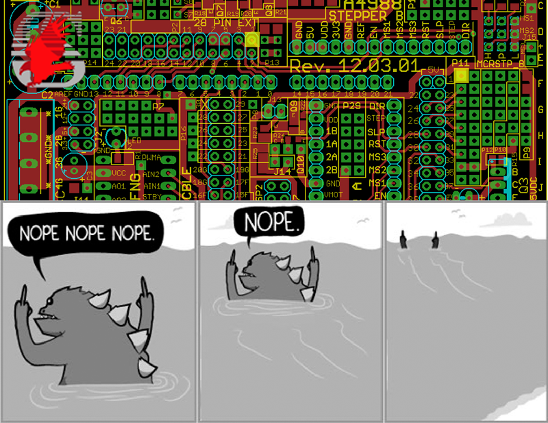
Well, not Eagle CAD. Not that it is not a good software, but we’d never touched it previously and the learning curve looked… steep… to us. The same goes for Kicad or gEDA (which are both open-source, which is nice)
Fritzing looked like a too easy solution but turned out to be pretty much exactly what we needed: it had a library of common components from Sparkfun (our beloved source for everything electronics) and others, and was pretty ergonomical to use.

After a few hours spent on various tutorials, Fritzing looked fit for the job.
Now, what need we design again?
The Raspberry Pi have digital pins and the sensor is analog. That means we need some kind of ADC between these guys so they can talk together. Actually that means that either we need an ADC that can convert 20-ish signals in parallel, or we need 20 little ADCs, one for each signal. Great.
Our preliminary structure looked a lot like that:
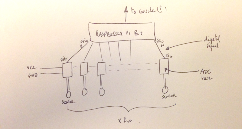
20 ADC, powered or not (but we had a feeling it would need power somehow) sending digital signals to the Raspberry Pi GPIOs.
A thorough look at the datasheet of the MiniSense 100 sensor gave us a lot of information:
- it behaves like a power source
- it can create a very large voltage between its pins (> 90V)
- it’s not really calibrated when it comes down to detecting “shocks”
So…
- we need to limit the output voltage somehow, since a Pi pin only accept 3.3V max
- we need some way to “calibrate it” so that it triggers the pin only above a threshold that we decide.
If we have to decide the threshold, that means we have to compare it to a reference tension. So we need a reference tension somewhere. And something that compares.
What about an operational amp mounted as a comparator?
We need one op amp channel per sensor, but for the reference tension, our first idea was to put it on each PCB, but then we thought: “it should be the same tension for every sensor board” so why not putting it before and only set it once somewhere?
And anyway the op amp needed power (ahah, we knew it!) so we needed another “main” PCB between the Raspberry Pi and the trigger boards. This PCB would allow us to breakout the Pi’s GPIOs nicely and maybe use nice connectors too, instead of 0.1" headers that would likely disconnect and break.
So, in a nutshell:

This design seemed to work (theoretically at least), so we started laying out the necessary components:
On the trigger board (the one for each sensor):
- an amp op to compare the signal of the sensor to a reference voltage
- a zener diode to limit the output of the sensor to a sensible 5V-ish
- resistors, because who doesn’t love resistors
- led as a nice visual indication of the “trigger” and as a quick and easy way to limit the current output by the amp op to a reasonable 20mA (the amp op like this one we used could brick our GPIO pins that cannot sink more than ~16mA per pin (see this for instance)
And on the bus board (the big one with the pin breakout):
- leds, more leds
- a ref voltage source, basically a variable adjustable resistor
- some Dupont headers to connect the Raspberry Pi and the sensors to it
At this point it is important to note that producing the PCB would take something like two weeks, including shipment. Which means: we have only one try ;)
Ok so, we put ourselves to work on the PCB and in parallel started to try to talk to the Playstation 2.
D - 25
ROGER, we have a SPI problem!
Our first findings on the web about how to “communicate” with a PS2 lead us in the realm of SPI.
The SPI Bus (Wikipedia article) is a full duplex serial bus where a master can communicate with several slaves over ~ 3 + number_of_slaves wires. It is quite well defined and implemented in various equipments such as sensors, video game controllers, LCDs, camera lenses, etc.
It can operate at practically any speed (the master dictates the speed of the bus).
Thanks to this old and fantastic technical document from Andrew J McCubbin we had a good starting point to understand how Sony had implemented SPI for the PS2.

Hello? 1998 just called!
So with this information, we found out that we could not use the de facto SPI standard because Sony had added an ACK paradigm, where the slave must acknowledge approximately everything it receives when it receives it.
So out goes the standard SPI libs for Raspberry Pi B+ that do not support any ACK line.
So we needed to code the Sony SPI protocol in order to interact with the console. Theoretically, not a very hard task: the bit sequences were apparently quite simple and deterministic, so we just had to bitbang everything through a few I/O pins.
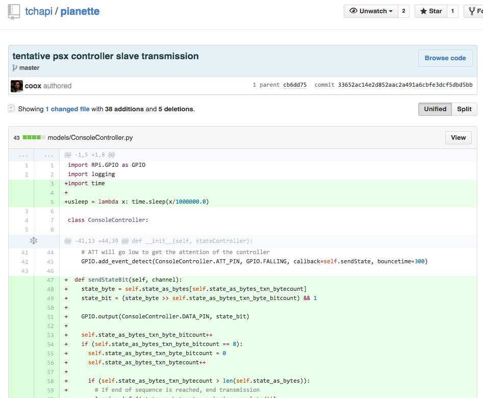
But after a lot of debugging we couldn’t make it work, the PS2 was not acknowledging any button we pressed (emulated), and did not react at all whatsoever.
That’s the problem when you can’t really know if you’re doing it right. Trial and error takes a lot of time and often, don’t work. This part of the chain and the way we wanted to address it was flawed by design.
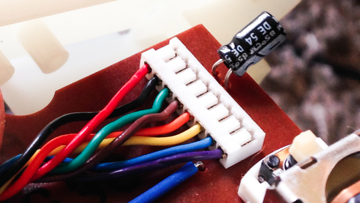
The inside connector of the Playstation 1 & 2 controllers
Our bitbanging sequence was pretty much correct, but somehow the PS2 didn’t see it. We decided to investigate further to see what could be wrong.
A look at the Curious Inventor guide led us to this interesting part that we didn’t take into account at first:
“Clock: 500kHz, normally high on. […] When the guitar hero controller is connected, the clock rate is 250kHz, which is also the rate the playstation 1 uses.”
Ok. 250 / 500kHz. What can the Raspberry Pi do?
Well, Joonas Pihlajamaa had an answer to that after a very intensive testing session: 44kHz (using Python).
Oops.
So what now? We can’t use the hardware SPI of the Pi and bitbanging in Python (or any other language, btw) is not fast enough. So we took a shot at adding a man-in-the-middle Arduino to do the fast SPI stuff. The good thing about the SPI library on the Uno is that you get a nice interrupt where you can add some code (provided that your code is not too long so it doesn’t mess up with the next interrupt), so it becomes easy to add an ACK as apparently required by the Sony version of the SPI protocol:
/* SPI interrupt */
ISR(SPI_STC_vect) {

  // Byte received from the master
  uint8_t inbyte = SPDR;

  // Here we can put more code like the ACK
  // But not too much, he, or we will miss
  // the next interrupt (*sigh*)
}
(Full code on github)
The serial communication with the Pi is done via the USB port and it doesn’t need to be very quick since we only send two bytes that are stored on the Uno for the next interrupt. The full SPI sequence is at least 6 bytes (see Andrew’s technical details), which takes at least 6 * 8 * 2 = 96 clock cycles, hence we can communicate with a speed of 500 kHz / 96 =~ 5kHz. A 38400 bauds serial will be perfect.
D - 24
A fully working hardware chain
To sum it up, 24 days before the event was scheduled to happen, we had:
- the sensors, 20 of them, attached to a little PCB that acts like an analog trigger and outputs a HIGH or a LOW depending on a threshold voltage
- a logic board that splits all the I/O of the Raspberry Pi and gives the threshold voltage (among other things) to the sensor boards
- a Raspberry Pi that is the central brain of the chain. A python app gets all the data from the I/O (ie, the sensors) and processes it, then sends it to an Arduino connected via the USB port
- an Arduino Uno, acting as a SPI slave with an ACK line
We had tangible proof that everything was working as expected:
When we “hit” a sensor (emulating what would be a piano hammer), the little comparator that we had set up previously worked like a charm: it converted the signal to a 3V3 HIGH or LOW depending on the threshold voltage that we set.
The Raspberry Pi gets the signal on one of its I/O pins setup as an input and processes it. If, say, the key was a simple “LEFT” on the controler pad, we create two bytes that correspond to the controler state for only the LEFT button pressed, and the Pi sends these two bytes to the Arduino via the serial communication channel.

The Arduino receives the two bytes and place them in a buffer while in the main loop. As soon as an SPI interrupt arrives (that is, the console is asking for the state of the controller), the Arduino sends the two bytes to the console and clears its buffer, allowing for the next controller action.
So we were beginning to have some level of certainty about most parts of the overall system. Now, we had a mere 3 weeks left to package the whole thing and create the PCB and casings, and to create a real firmware that will process not only the sensors but sequences and combos through different chords played on the piano.
D - 23
The “revision 01” only chance
In parallel, we had worked on the electronics and now had a first version of the two different PCBs: Revision #01.
Each “trigger board” was a very simple circuit with the op amp:
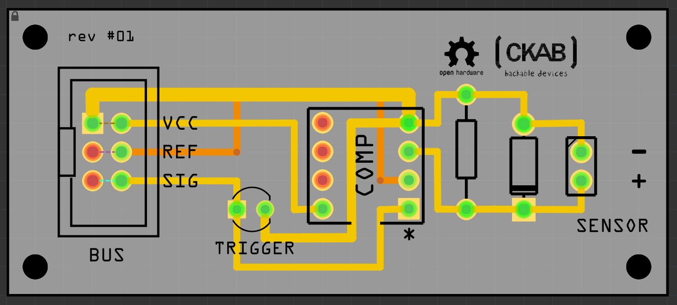
We had a led to indicate whether or not the op amp was saturating or not (ie. if the sensor output was above the reference voltage) but forgot to add a required resistor to it (which was a mistake, though not a big one, hopefully). The other parts were pretty straightforward.
The “bus board” looked like a very large breakout of the different GPIOs of the Pi B+:

Each connector had a VCC and GND line, as well as the reference voltage, and the GPIO in itself. Nothing very fancy here.
It seemed logical to source VCC from an external power source (top right bit) and not from the Pi since the GPIOs could not deliver a very large current.
We had put a connector for the SPI lines (top left) in case, but as we figured out (see previous chapter) we wouldn’t be able to use it anyway.
In fact, we decided as well to create another PCB for the Arduino Uno, that would gather the different SPI pins in one handy connector for the Playstation 2:
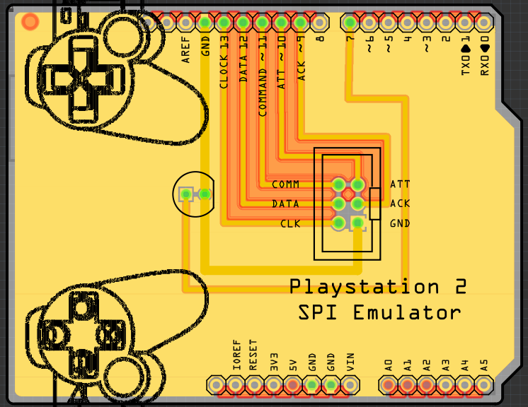
(Note the fancy silkscreen stuff)
We spent quite a long time verifying the designs as we knew we only had one chance — The whole batch was then sent to production in Germany at D-22 approximately. It was a blocking process since we knew we couldn’t really test anything without the whole set of PCBs. The big question that we had was: will our hardware chain still work with all the sensors connected at the same time?
D - 20 to D - 12
A quest for the beautiful and practical
While waiting for the PCBs, we had some free time on our hands. A good opportunity to take care of another important factor of success for the installation: the looks.
We needed to protect the electronics from the public (pianists mainly) and as well find a way to hook the whole system to the pianos.
We had a few techniques at our disposal, mainly 3D printing, laser cutting and wood-working, either in-house at CKAB, or at partner fablabs such as Draft.
In a nutshell, we had to create:
- casing elements for the trigger board: 20 per piano = 40
- a way to attach the triggers to the piano frame
- casing elements for the bus board: 1 per piano = 2
- casing elements for the Arduino and its shield: 1 per piano = 2
- casing elements for the Raspberry Pi: 1 per piano = 2
We went the easy route for the Pi and bought 2 cases off the shelf for about 10€. There were no cases that would fit an Uno + a shield (or we didn’t find any that would suit our need) so we had to make one.
Arduino case
This was pretty straightforward. We created a laser-cut enclosure similar to this one created by teabot, that consists of 6 panels hold together by a set of screws, and some spacers and screws to tighten the board to the bottom panel:
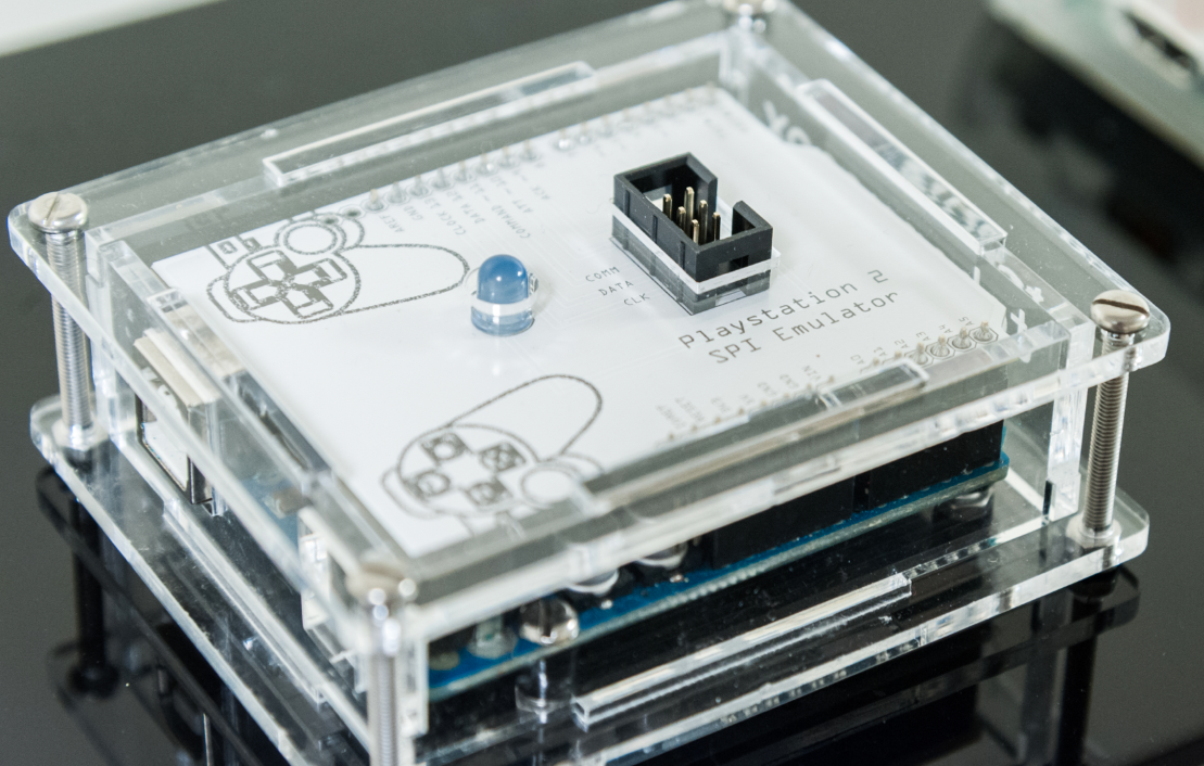
Screws used are M3 of various sizes
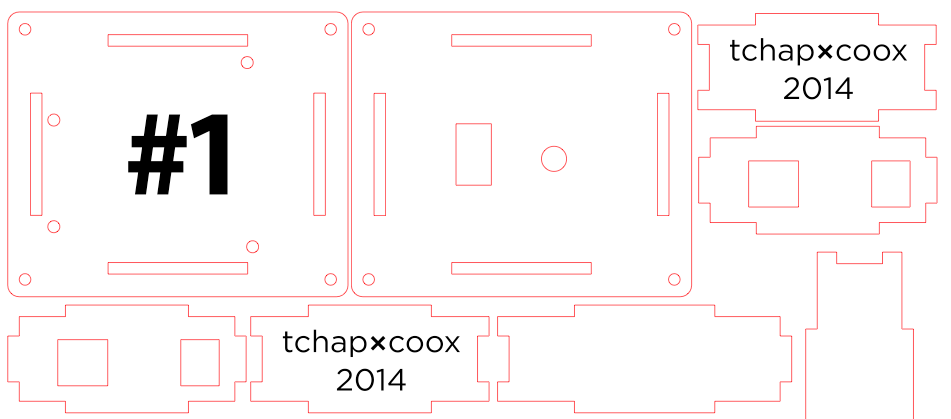
Extract from the AI file. Red is cut, black is rastered
Two holes were left in the top panel for the status led of our shield, and the connector (to the Playstation).
Bus board case
The bus board needed a casing that would hold it in place and limit the bending of it (it is 30cm long!). So we figured out we had to attach the PCB not only at the outskirts but all along the length.
We came up with this simple design that did the job (top and bottom panels represented below):

Again this is only laser cut. 30cm of width was too big to fit in our printers anyway, so we didn’t really have a choice.
With the final PCB inside (see below):
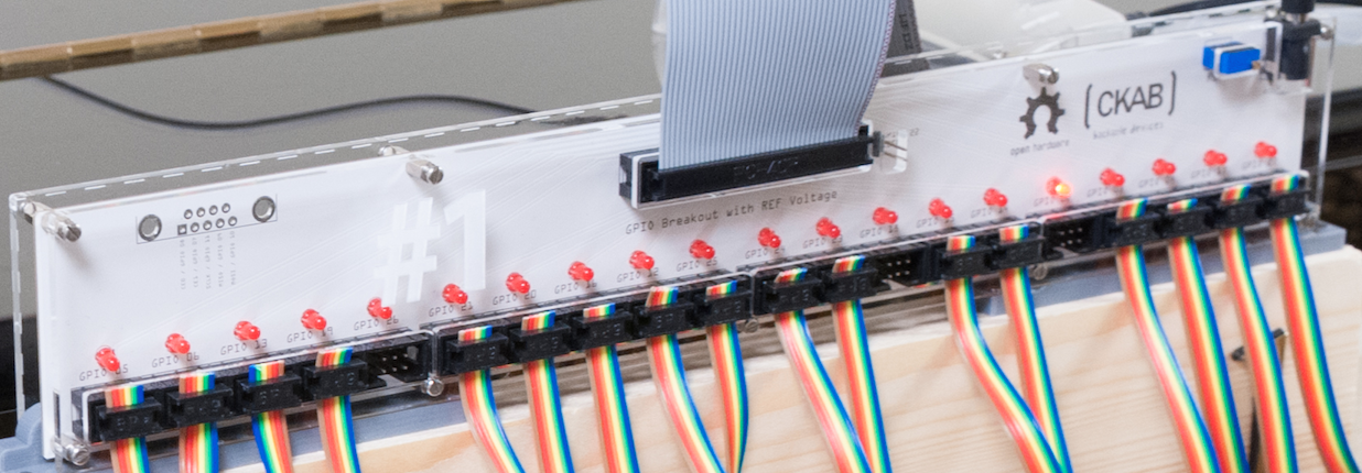
Wood frame
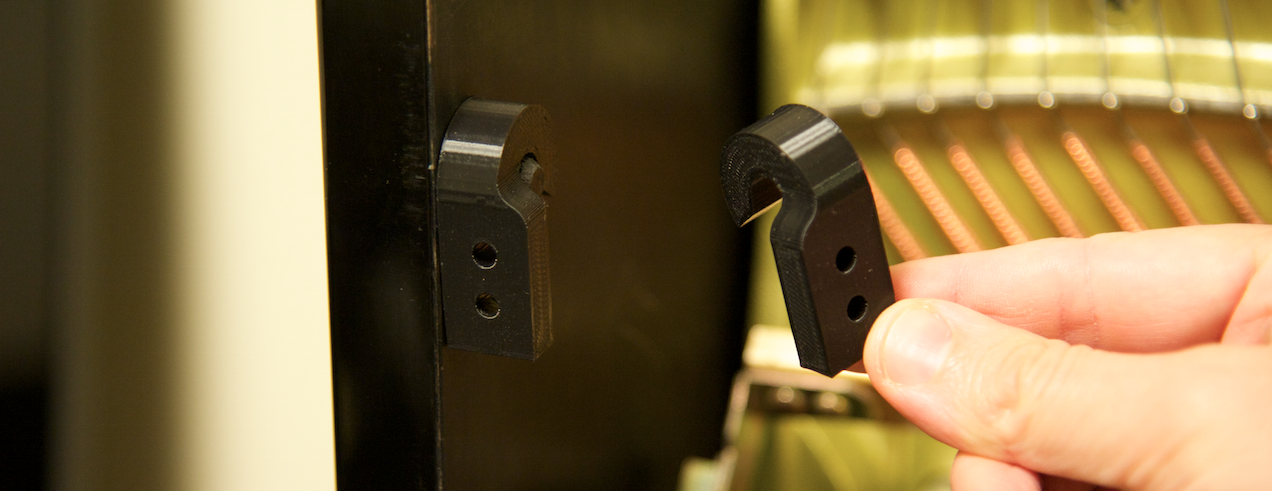
To attach the whole system, and especially the triggers, we needed some kind of heavy duty frame that we could easily hook to the piano. We thought wood would be the perfect fit for the job.
A few bucks later and we had a wood panel that would clip onto the existing tenons with a custom printed plastic part:

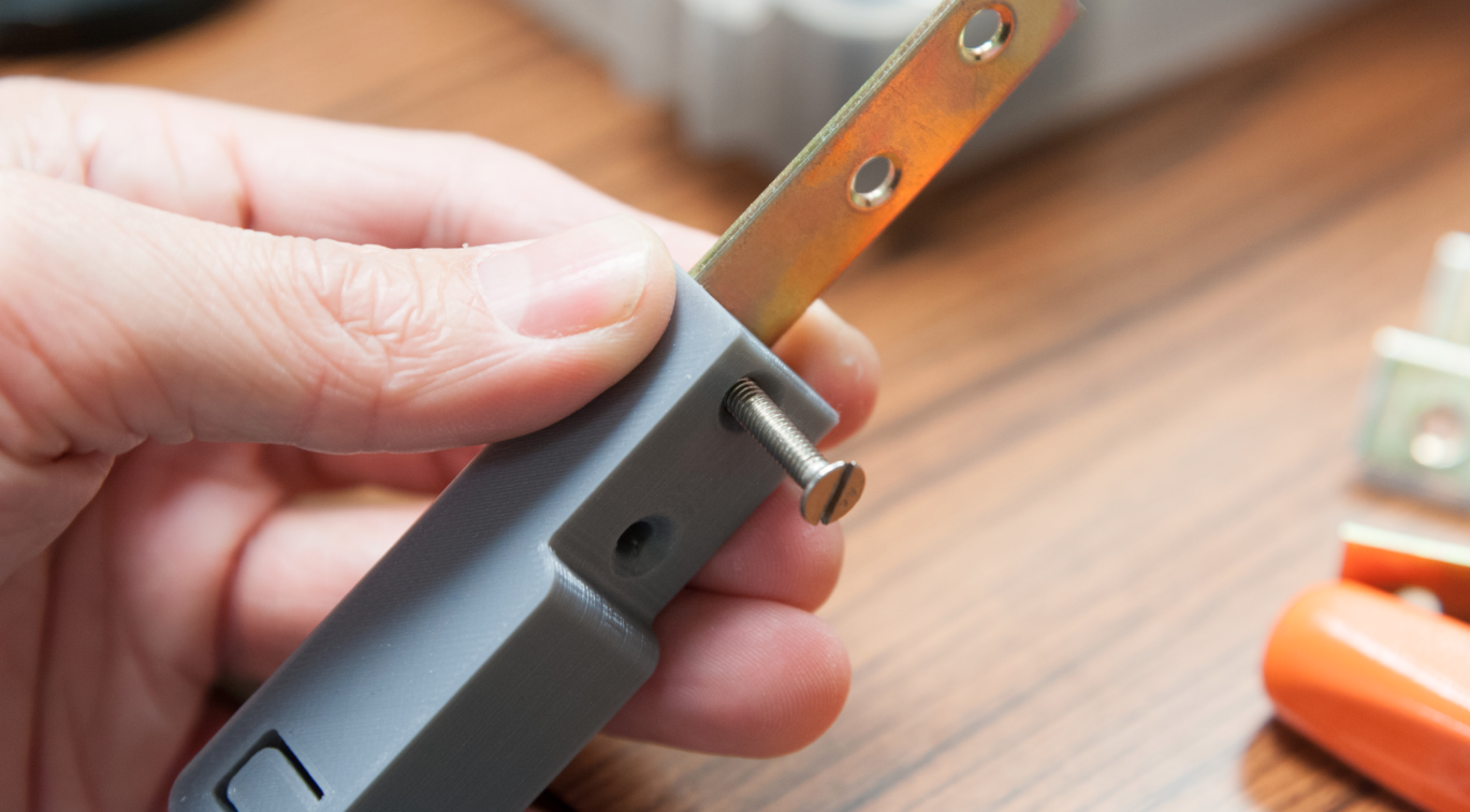
Then attached to this, a rail to hang the triggers on (a few bucks in a hardware store):

…again with a custom part made in plastic and a steel plate:
Trigger board case
These parts were small enough to be created in whatever technique we’d fancy. But we figured out that creating 40+ protective elements in wood would take us quite a bit of time and would cost a lot of money. 3D-printing them was definitely an option but would take quite a bit of time as well compared to laser-cutting. But we needed to find a way to hook the board to the rail, so cutting only flat pieces of plastic was not enough. We thus decided to combine both techniques: main parts laser cut and a little “sliding” part in 3D printing. Best of both worlds.
We even bought colored acrylic to pimp up the casings \o/ and separate them in 4 groups.
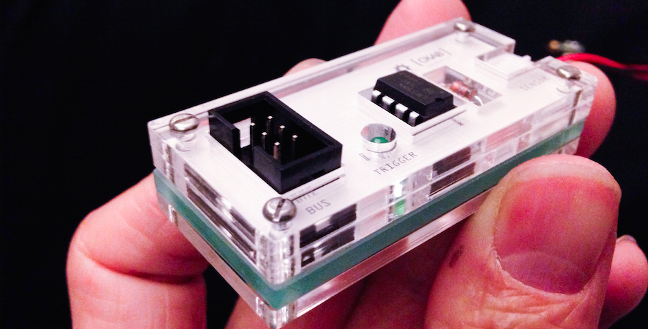
A view of the casing with the PCB already inside
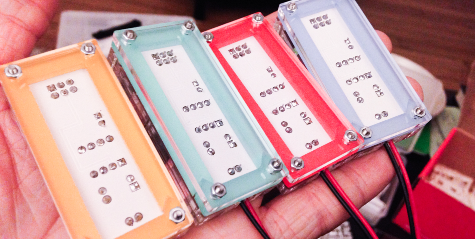
The rear
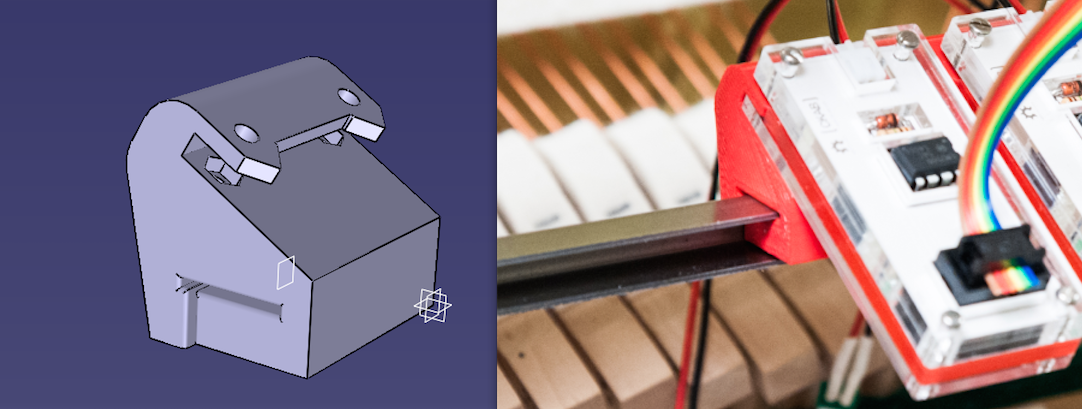
… and the 3D printed part (left and here), to hook up the casing to a rail, and right the two parts of the casing together with the PCB
We needed about 2 square meters of clear acrylic, and about 1kg of PLA.
D - 12
Soldering the electronics, and assembling
The PCB we received were pretty much what we expected (hopefully):
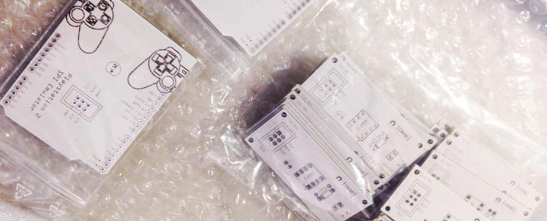

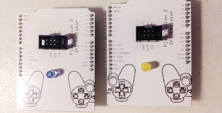
We spent at least 3 full days soldering and testing each board. To our great astonishment, everything went well and was working properly.
We now had all the necessary parts of the system. Except… the two pianos, that would arrive only two days before the event.
Ouch.
D - 10
Firmware (re)factor
At this stage, through this custom built hardware, it was possible to map what-would-be-piano-hammer strokes to straight PlayStation control hits. So hitting one given piano note would translate straight to hitting one given controller button or direction key.
This was a great start, but as we had determined since our very first meeting, it was not enough to satifyingly fulfill our vision. Our prototypal firmware required improvement because:
- a skilled piano player wants to play chords (several notes at the same time) to set harmonic basis and mood to the music
- a skilled Street Fighter player wants to play combos (timed combination of keystrokes) to hit their opponent in spectacular fashion
We also figured that, as the date of the event was getting closer and closer, we would iterate more and more on polishing the gameplay experience, rather than the hardware and software underneath (at least we hoped so). So we decided that the firmware required another kind of improvement: more flexibility and more configurability.
The state of configurability before the refactoring was as shown in the code below:
# Mapping
KEYS  = {
  15 : "T",
  3 : "S",
  5 : "X",
  6 : "O",
  7 : "TOP",
  8 : "BOTTOM",
  9 : "RIGHT"
  10 : "LEFT",
  11 : "SELECT",
  12 : "START",
}
Single Raspberry Pi GPIO pin numbers (left) are mapped to single a PlayStation 2 controller buttons (right).
Pretty straightforward, but leaving no room at all for anything else than exactly this exact and basic feature. No chords, no combos, not even a mention of any concept related to music! Moreover, it was buried in the code.
To tackle this situation, we decided to adopt a clear and strict separation of concerns, in which our firmware would be conceptual center of command:
- the single role of the piano is to play notes (key hits)
- the single role of the console is to play controls (button hits)
- the role of the pianette, our firmware, is to receive notes from the piano, somehow turn them into controls, and send these controls to the console
That became the basis for a refactor of the whole firmware.
To begin, we moved the mapping to a dedicated configuration file, and used the configobj module, which allows for “deep” configuration objects.
Being at both ends of our project, the piano and the console were configured to expose what input/output they could possibly provide/expect. So how do you represent piano keys and console buttons in a configuration file? We gave it some thought, and ended up using what we thought was their most immediate representation:
[Piano]
supported-notes = C1, G1, B♭1, C2, C3, D♭3, D3, E♭3, E3, F3, G♭3, G3, A♭3, A3, B♭3, B3, C4

[Console]
supported-controls = ↑, ↓, ←, →, □, △, ✕, ◯, L1, R1, L2, R2, SELECT, START
For writing notes, we really wanted to use a score sheet. But that proved too difficult to do in a text configuration file that was also intended to be edited quickly. So we used a combination of latin letters, traditionally used in English-speaking countries for representing note pitch, paired with a number representing the traditional numbering on a standard 88-key piano. In our context, these entries unambiguously represented music in a short and expressive way.
Notice that we didn’t cheat: we used the actual ♭ symbol for flat (we could have also used ♯ for sharp). It’s the kind of detail that we really enjoy injecting in our project, as a humble hommage to the work of giant inventors who allow us to do so in the first place.
In the same manner, we wanted the configuration entries for the console to be an unambiguous representation of controller buttons. Drawings speak louder that written words, so we went the glyph route. Unicode is a treasure, and we knew it included arrow symbols, so we naturally used them for direction buttons.
PlayStation consoles are notorious for their set of four buttons with shapes of square, triangle, cross, and circle. However, to our disappointment, we found no endpoint for these, so we used what we judged to be the closest approximation: WHITE SQUARE (U+25A1), WHITE UP-POINTING TRIANGLE (U+25B3), MULTIPLICATION X (U+2715), and LARGE CIRCLE (U+25EF).
So now we had a clearly defined contract of our input and our output, and it was fully configurable! The difficulty, of course, still resided in the way to somehow turn notes into controls.
D - 9
Combo me out
In order to make the game fun to play at all, it was a requirement for the firmware to issue not only simple controls straight to the console, but also combos.
What are combos anyway? In the Street Fighter game series, single buttons trigger a single move or strike, but experienced players know that certain sequences of buttons are key to produce more powerful attacks. For example, the main protagonists (and rivals) Ken and Ryu can send some sort of fireball if the player correctly executes a quarter-circle movement from the ground towards their opponent, ending the sequence with a hit on one of the punch buttons. This move is know as “Haduken”, and is one many combos available. Their variety adds to the depth of the game, by showcasing characters by their distinct style. Without a doubt we need them!
Our first problem here was that combo support required management of a whole new concept in our firmware: the concept of time.
Conceptually, that was not so difficult to solve. We enhanced our firmware to support buffered output to the console. By buffering upcoming controls to be sent to the console, and by popping the next available buffer entry at each iteration of the Pianette main loop, a single piano note could trigger a programmed sequence of console controls… In theory, at least.
In practice, of course, it didn’t quite work out on the first attempt. The console appeared to skip some of the controls that it was sent. Timing is everything, and it took a few iterations of trial and error to determine a buffer cycling frequency that made the console respond consistently. We observed that in practice, this happened using a duration between ~7ms and ~26ms for our button hits, so we settled on the intermediary value of 15ms in an attempt to maximize predictability.
That worked pretty well for single controls, not quite yet for combos. We figured that probably, the console was discarding part of the controls because most players can’t hit the buttons that fast. While that was fun because it already opened the possibility of “superhuman” gaming, we had to push a little more and find better “human behavior” emulation. Turns out, letting a button “pressed” during three cycles (ie. 45ms) did the trick. The outcome really started to feel like magic.
_A single control turns into a combo for the first time_Under our amazed eyes, any single piano key could now send any combo to the game!
D - 7
Strike a chord
Our focus was always to transport the expressivity of a piano player straight to a video game. We figured that for a user of our system, their ability to play a game should be the direct reflection of their ability to play the piano. It was up to us to figure out how exactly.
One very tangible way of injecting the expressivity of a pianist into the game would have been to make the fight as intense as the volume of the music they play. The louder the notes, the stronger the attacks. However, our choice of piezo-based hardware resulted in all notes reaching the firmware with equal velocity. So, unfortunately, that lead was a no-go.
How else could we proceed?
Beginner Street Fighter players struggle using one-time strikes. Advanced players master well thought-out combos. Just as much, we thought, as beginner piano players struggle with playing single notes in coordination, while advanced players master emotion-provoking chords (but not only, of course). That was it! We needed to support chords in the firmware.
Progression of chords can heavily influence the mood of a piece of music. A minor chord within a major scale progression could makes the mood melancholic for instance, but add power. Enhancing a major chord with its 2nd makes you suddenly feel hopeful. Some chord progressions even make the listener beg for a satisfying resolution. Like combos in Street Fighter, they are a weapon of style.
We wanted to keep our firmware configuration system very readable. To convey the notion of simultaneous piano note being played, we chose to introduce the + operator. A satisfying choice because of its simplicity, and also because the operator could, in symmetry, be applied to console controls as well.
And so we began implementating support of:
[[Mappings]]

# Tatsumaki Senpuu Kyaku
D3 + F3 + A3 + C4 = ↓ ↘ → + ✕ # Dm7
Remember that our firmware consists of a main loop running on a period of 15ms, that reads inputs from piano keys, and buffers resulting control sequences for the console. In theory, it shouldn’t be too much harder to support reading several piano key inputs if we can already read one, right? Well, as always, practice makes a difference, and timing is everything. Is it safe to expect that our piano players can consistently produce chords during a single window of 15ms or less? Not quite.
So we figured that we had to allow inputs from the piano to be read during a slightly longer period of time. However, this was likely to have a direct impact on gameplay. Not too much time could happen between the moment a pianist hits a note and the moment their character reacts in the game: we didn’t want to make the game feel sluggish.
There was also another challenge to solve. Let’s pretend that we want to support the following mappings:
C3 = □  # Weak Punch
B3 = ✕  # Weak Kick
C3 + E3 + G3 = △ △ △ △ △  # C maj chord: Five Strong Punches
E3 + G3 + B3 = ◯ ◯ ◯ ◯ ◯  # E min chord: Five Strong Kicks
It’s pretty readable and resonably describes what we want to happen if the pianist plays within the combinations listed. But what do we want to happen if:
- the pianist plays a combination of both
C3 + B3? - the pianist plays a C maj 7 chord, which is a combination of both configured chords:
C3 + E3 + G3 + B3? - the pianist plays a C maj chord, then immediately an E min chord, then immediately a
C3note?
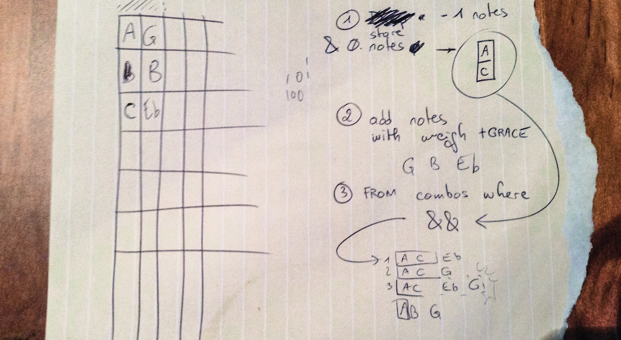
(a peek into the life of developers trying to solve a problem)
These questions need answers because the firmware must do something. But the answers we were looking for were the product of more than sole research and equations. Designing the firmware was more like writing a philosophy book than a calculus book. It was up to us to decide what rules to go by.
We figured that there was a series of input patterns that required first-class handling, for the sake of the project. So we took opinionated decisions about them, and injected them into our input resolution algorithm:
conflict: What if the player requests their character to strike both a kick and a punch at the same time, like in the first question asked above? We decided that this was the game’s job to decide, so that case is delegated by sending all controls to the console!
priority: What if the pianist plays enough keys at the same time that several listed combos are matched, like in the second question asked above? To encourage player skill development, we decided that priority is given to combinations with the highest count of piano notes. And to open the possibilities of game fine-tuning, ties are broken by order of declaration in the configuration file.
breakage: What if the pianist plays anything during the execution of a combo, like in the third question asked above? We decided that it would feel more like a game if we let the players fully express themselves. So we send any additional control along with the combo in progress, and once again let the console decide what to do with it.
Have a look at the code to see how we eventually meshed it all!
With all the pieces of this solution combined, the pianist has a chance to hit the piano, and their move will happen during a window of 16ms (best case) to 30ms (worst case). This was a compromise that seemed to offer great gameplay opportunities, and we are still quite happy about it.
D - 5
The “shell”
Only a few days to go and we had no piano to test the whole setup yet.
So what did we do? We created a virtual input, the pianette shell.

The main benefit, apart from being cool, was that it made manual testing easier, and automated testing possible. Apart from an interactive shell, we were able to run batches of commands to simulate user input in a timely fashion, thus verifying that everything was OK after each code change or hardware tweaking.
Example:
pianette: console.play START
pianette: game.select-mode Versus
pianette: game.select-fighting-handicap ▶▶▶▶
Or:
pianette: piano.play C4
pianette: time.sleep 1
pianette: piano.play C3+E3+G3
So yeah, we figured that even though this project was intended for the short-term under a tight schedule, we could still afford the possibility to apply some best practices.
And we even reaped their benefits! Support for scripted commands based on GPIO events is how our “big red button” works behind the scenes.
D - 2
The first real test
Enough code. Let’s get back to the hardware.
The full system, including both pianos, was tested for the first time only two days before the event.
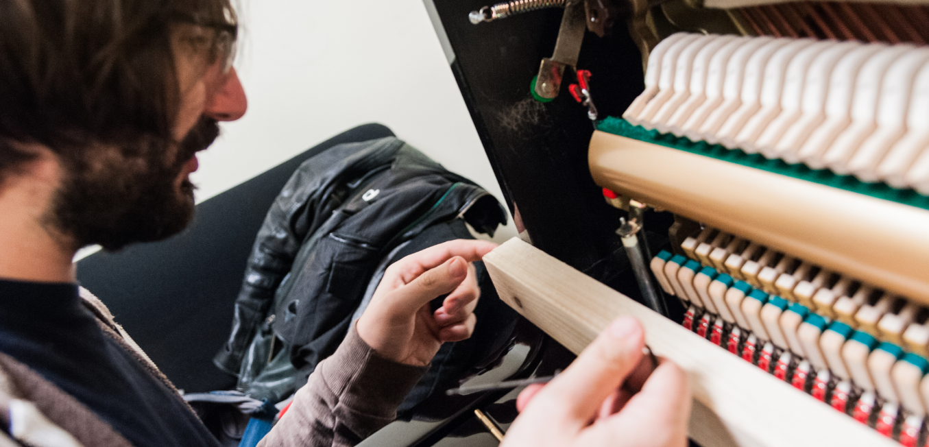
We first had to assemble everything: triggers, bus board, all on the wood frame:
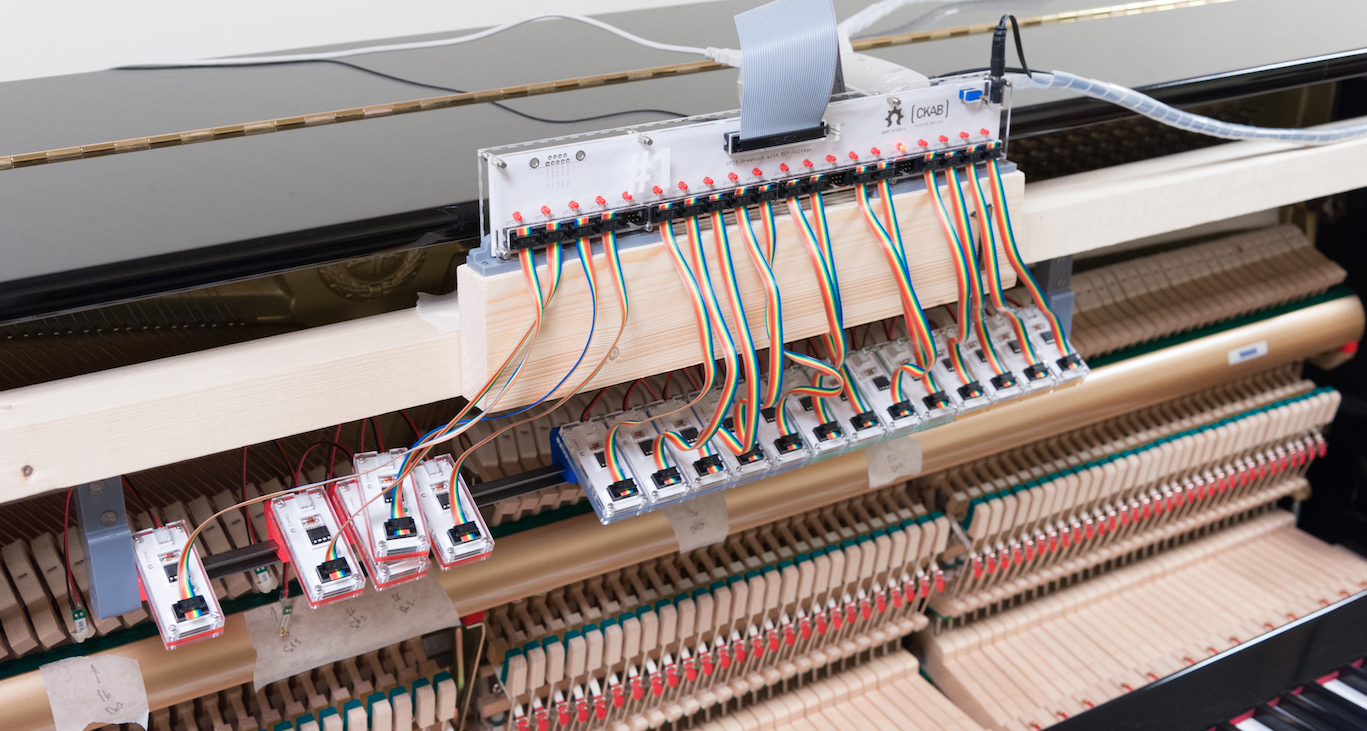
And then wire everything together:
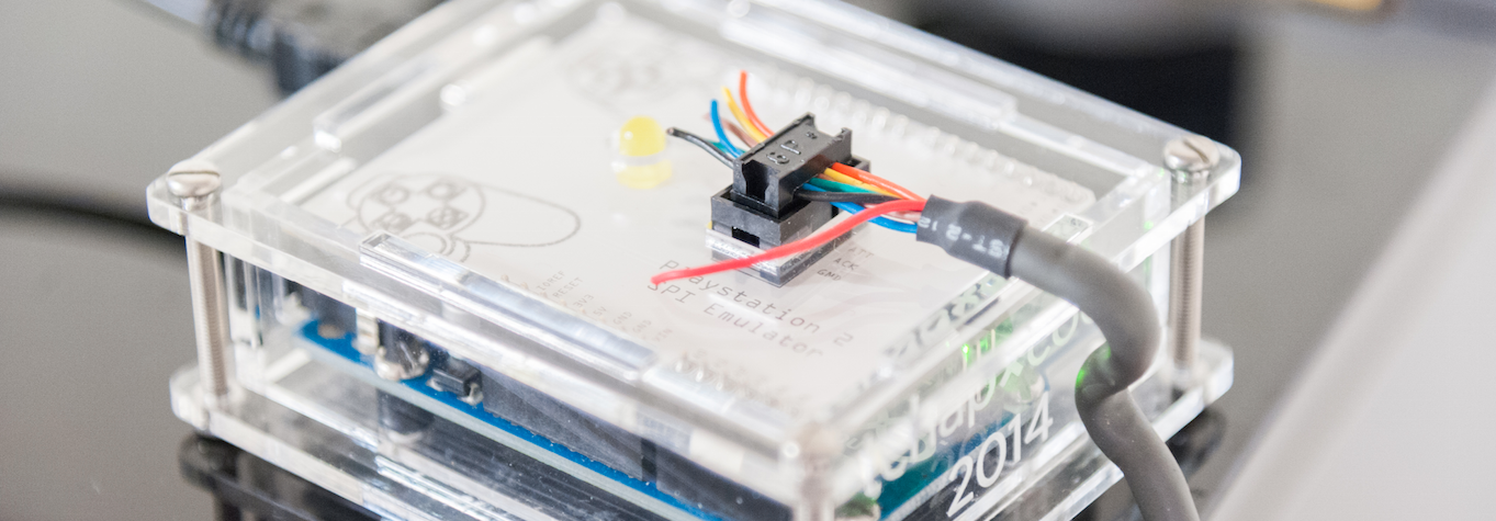

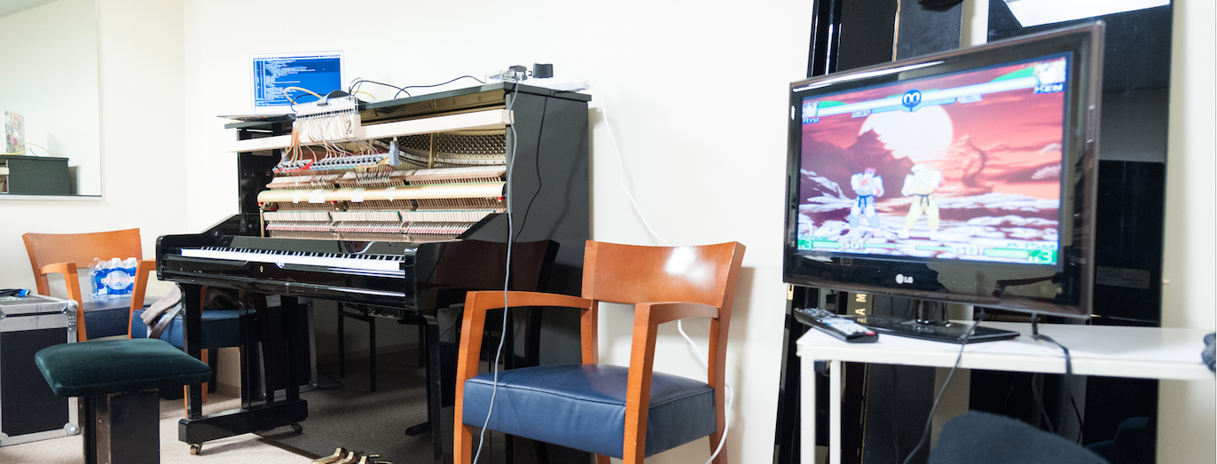
The system was ready to test! Let’s play some… arh… Sound Fighter!
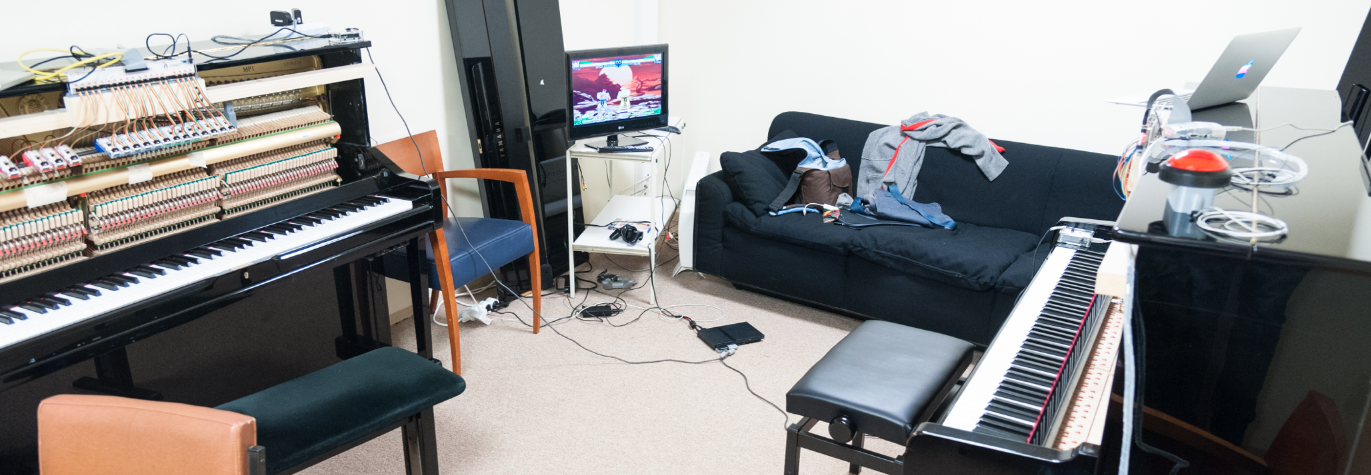
Some adjustments were made:
- combos, obviously: timings and chords attached to different moves and actions <TODO: AKA timing is everything PART 2, settled on a 45ms output duration + 15ms cycles + 2 period input buffer>
- cutting some ground loops to reduce EMF interferences and such
- adjusting timers and speed of movements for each left hand keys to have a better gameplay
D - 1
Oh. Sh*t.
But after a while, problems started to emerge:
- random resets (we had created a special “reset” combination to emulate a player going back to the menus and choosing a special mode and character automatically, and start the game)
- some keys “harder” to trigger than others
- the Raspberry Pi not connecting to the console via the Arduino every other boot
- some disturbances from time to time…
This last day before the event was really stressful and we made the mistake of not following a simple rule for debugging: repeatability.
(oh, the headaches we got)
So we ended up testing bugs that were completely different each time because we did things differently everytime. That’s the moment when the Open Source community really helped!
To make a long story short, what we eventually discovered:
- like we said before, some I/O pins on the Raspberry Pi had a different pull-up resistor (a hard wired one, actually, I2C I’m looking at you) that prevented two inputs to work properly. We had to change the input binding and not use these pins. Hopefully we had 3 pins more than wired keys so it didn’t really pose a threat to the whole system
- to make the special reset combination, we had wired a big red arcade button (this one) tied to one of the pin, and a push on the button made the pin go LOW to activate the reset. That is a bad idea. In case of brownouts (due to, for instance, some disturbance in the input power), all pins tend to have a lower potential, and that usually trigger a LOW state for the pins. So this pin would trigger in case of a brownout, whereas all the key pins were driven HIGH when triggered, so they didn’t really feel anything; Note to self: always trigger on a rising edge when you may have brownouts!
- everything works far better when we connect it in the same order, everytime we connect it (Arduino, then Pi, then power on the main board…)
sudo haltis actually important when you work with Raspberry Pis…
<TODO: - enable_source/disable_source at firmware level>- a complicated hardware chain = complicated problems
The best practices that we talked earlier, well, we definitely should have applied them to the hardware too! ;)
H - 2h
Final assembly and live event
The final on-stage assembly went well and the system was near fully functional when we opened the gates.
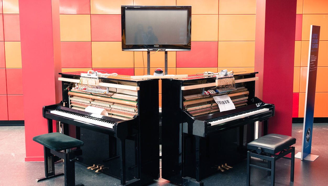
(the screen here is different than in the video at the beginning of the article — we installed a special set for two professional pianists with a 4m×3m screen, the one above was used during the open house)
We still experienced some cold sweats when a few resets happened, most likely due to large spikes in power (a live radio show was starting in the adjacent open air studio, etc.). But we saw no more than three during the course of the 4 days we were animating the installation, which we consider quite good.
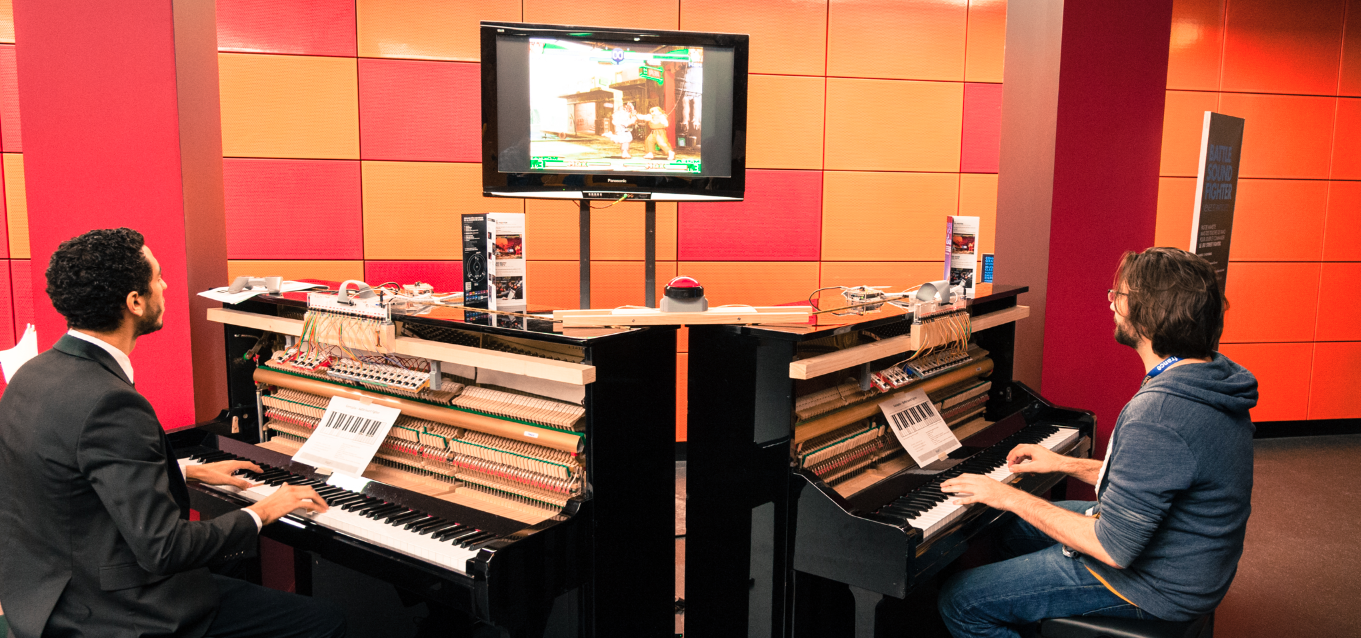
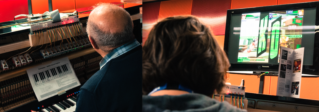
A lot of people did come to see and play. It was very rewarding to witness so smiling and puzzled faces alike, as well as so much engagement, curiosity, and fun in the audience:
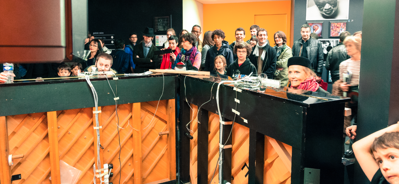
One of us fighting a random contestant:
Final words
We’re proud of our work and the fact that you have read everything up to here (wow).
We'd like to express a big thanks to our loved ones for supporting us along the way ! And as well for taking some of the pictures that helped documenting the whole process.
The code is released under the MIT License here. The hardware files too (same place). We would be delighted if you ever use the system or part of it in one of your project, for example if you would like to contribute a configuration for another console, create a different set of chords that would fit Street Fighter better, or even adapt for other games and instruments (playing Metal Gear Solid 2 with a flute? GTA with a drum set or Final Fantasy with a clavinet?)
This whole installation should be considered a “beta” version, somehow. A lot of improvements are possible, for the hardware of course, but also in the firmware that we wrote. Some thoughts on the top of our heads:
- creating a system of pipes/filters
- having more factorized controls
- adding support for “velocity” (i.e. strength of the note) that could be configured this way, for instance:
D3 + F3 + A3 + C4 = ↓ ↘ → + ✕  # Dm7
{D3 + F3 + A3 + C4}(p) = ↓ ↘ → + △  # Dm7 (piano)
{D3 + F3 + A3 + C4}(ff) = ↓ ↘ → + R1  # Dm7 (forte)
- a lot of other things ;)
The ultimate goal of this project, if ever we find time and resources to work on it a bit further, is to create something wider and more versatile that could accept many input channels and, why not, different output channels as well.
Interested? Drop us a line!
cyril[at]foobarflies.io + eric[at]foobarflies.io
